SiBE121135 Indoor Unit
Printed Circuit Board Connector Wiring Diagram 59
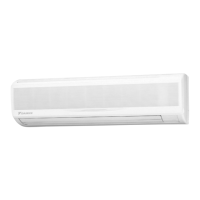
2.8 FDXS25/35E7VMB, FDXS50/60C7VMB
Connectors and
Other Parts
PCB (1): Control PCB
PCB (2): Display PCB
1) S1 Connector for AC fan motor
2) S7 Connector for AC fan motor (Hall IC)
3) S21 Connector for centralized control (HA)
4) S26 Connector for display PCB
5) S32 Connector for indoor heat exchanger thermistor
6) H1, H2, H3 Connector for terminal board
7) GND Connector for terminal board (earth)
8) JA Address setting jumper
∗ Refer to page 415 for detail.
9) JB Fan speed setting when compressor stops for thermostat OFF
JC Power failure recovery function (auto-restart)
Refer to page 418 for detail.
10) LED A LED for service monitor (green)
11) FU1 (F1U) Fuse (3.15A, 250V)
12) V1 (V1TR) Varistor
1) S1 Connector for control PCB
2) SW1 (S1W) Forced cooling operation [ON/OFF] button
3) LED1 (H1P) LED for HOME LEAVE operation (red)
4) LED2 (H2P) LED for timer (yellow)
5) LED3 (H3P) LED for operation (green)
6) RTH1 (R1T) Room temperature thermistor
 Loading...