Outdoor Unit SiMT041509E
11 Printed Circuit Board Connector Wiring Diagram
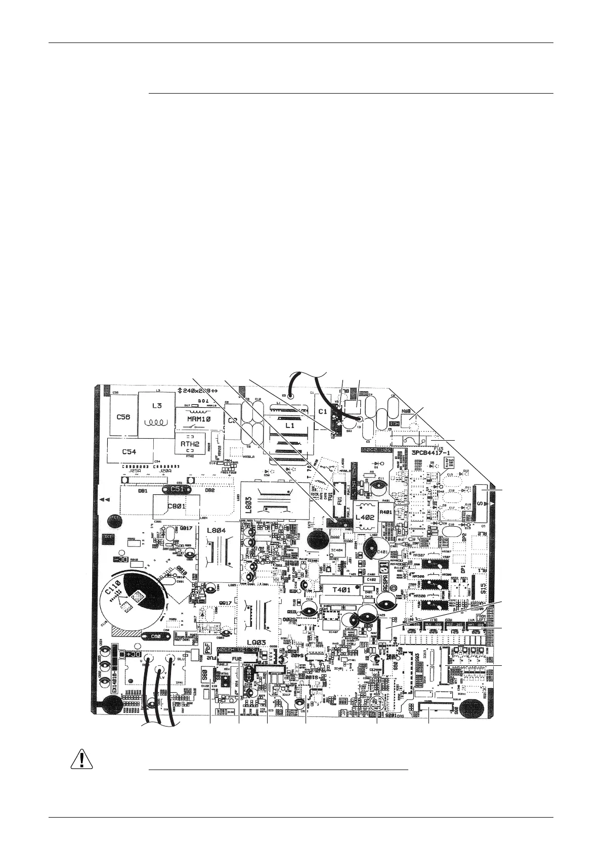
2. Outdoor Unit
Main PCB
Caution Replace the PCB if you accidentally cut a wrong jumper.
Jumpers are necessary for electronic circuit. Improper operation may occur if you cut any of
them.
1) S20 Connector for electronic expansion valve coil
2) S40 Connector for overload protector and high pressure switch
3) S70 Connector for DC fan motor
4) S80 Connector for four way valve coil
5) S90 Connector for thermistors
(outdoor temperature, outdoor heat exchanger, discharge pipe)
6) S92 Jumpers for local setting
∗ Neither disconnect the connector nor cut any of the jumpers.
7) S100 Connector for fan motor (for cooling electrical box)
8) HL1, HN1, S Connector for terminal board
9) E1, E2 Terminal for earth wire
10) U, V, W Connector for compressor
11) FU1, FU2 Fuse (3.15 A, 250 V)
12) FU3 Fuse (30 A, 250 V)
13) LED A LED for service monitor (green)
14) V2, V3, V401 Varistor
V401
FU1
V2
V3
HN1
HL1
FU3
S
S40
S20
S92
S90
LED A
S100
S70
FU2S80
UV W
E2 E1
2P387226-1
 Loading...