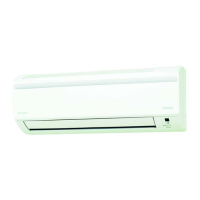
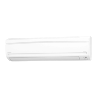
Indoor Unit SiBE041029EC
13 Printed Circuit Board Connector Wiring Diagram
Signal Receiver
PCB (PCB2)
Buzzer PCB
(PCB3)
Display PCB
(PCB4)
INTELLIGENT
EYE Sensor PCB
(PCB5)
Note: The symbols in the parenthesis are the names on the appropriate wiring diagram.
1) S29 Connector for control PCB
2) SW1 (S1W) Forced cooling operation ON/OFF button
∗ Refer to page 106 for detail.
SW1
S29
2P099167-1
2P290430-1
1) S27 Connector for control PCB
2) S38 Connector for display PCB
3) RTH1 (R1T) Room temperature thermistor
2P099167-1
2P290430-1
RTH1
S38
S27
1) S37 Connector for buzzer PCB
2) LED1 (H1P) LED for operation (green)
3) LED2 (H2P) LED for timer (yellow)
4) LED3 (H3P) LED for HOME LEAVE operation (red)
LED2 LED3
S37
2P099167-1
2P290430-1
LED1
1) S36 Connector for control PCB
S36
3P099913-1
 Loading...