SiBE041029EC Indoor Unit
Printed Circuit Board Connector Wiring Diagram 12
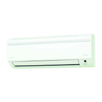
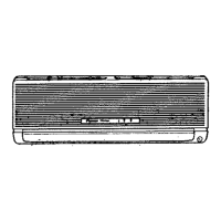
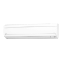
1. Indoor Unit
Control PCB
(PCB1)
Caution Replace the PCB if you accidentally cut the jumpers other than JA, JB, and JC.
Jumpers are necessary for electronic circuit. Improper operation may occur if you cut any of
them.
Note: The symbols in the parenthesis are the names on the appropriate wiring diagram.
1) S1 Connector for DC fan motor
2) S6 Connector for swing motor (horizontal blades)
3) S8 Connector for swing motor (vertical blades)
4) S21 Connector for centralized control (HA)
5) S26 Connector for buzzer PCB
6) S28 Connector for signal receiver PCB
7) S32 Indoor heat exchanger thermistor
8) S35 Connector for INTELLIGENT EYE sensor PCB
9) H1, H2, H3 Connector for terminal board (indoor - outdoor transmission)
10)FG Connector for terminal board (frame ground)
11)JA Address setting jumper
∗ Refer to page 108 for detail.
12)JB Fan speed setting when compressor stops for thermostat OFF
∗ Refer to page 110 for detail.
13)JC Power failure recovery function (auto-restart)
∗ Refer to page 110 for detail.
14)LED A LED for service monitor (green)
15)FU1 (Fu), FU3 Fuse (3.15 A, 250 V)
16)V1 Varistor
V1
FU1
S6
2P099167-1
2P290430-1
JCJBJA
S8
LED A
S21
S35
H1
S26
S28
S1
S32
FG
H3
H2
FU3
 Loading...