SiBE041029EC Outdoor Unit
Printed Circuit Board Connector Wiring Diagram 14
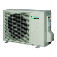
2. Outdoor Unit
2.1 RX50/60G2V1B, 71 Class
Main PCB (PCB 1)
RX50/60G2V1B
1) S10 Connector for terminal board (indoor - outdoor transmission)
2) S20 Connector for electronic expansion valve coil
3) S40 Connector for overload protector
4) S51, S101 Connector for service monitor PCB
5) S70 Connector for fan motor
6) S80 Connector for four way valve coil
7) S90 Connector for thermistors
(outdoor temperature, outdoor heat exchanger, discharge pipe)
8) AC1, AC2 Connector for terminal board (power supply)
9) HR1, HR2 Connector for reactor
10)E1, E2 Connector for earth wire
11)U, V, W Connector for compressor
12)FU1 Fuse (30 A, 250 V)
13)FU2, FU3 Fuse (3.15 A, 250 V)
14)V2, V3, V5
V6, V11
V9, V100
Varistor
(for 50/60 model)
(for 71 model)
V3
V11
AC1 E1 E2
HR1
HR2
2P169046-1
S40
S20
S70
S90
S51 W V U
S10
AC2
S101
V5
S80
V6
V2
FU1
(30A)
FU2
(3.15A)
FU3
(3.15A)
 Loading...