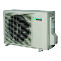
Outdoor Unit SiBE041029EC
15 Printed Circuit Board Connector Wiring Diagram
71 class
Service Monitor
PCB (PCB 2)
SW4-A has no function. Keep it OFF.
V3AC1 E1 E2
V100
2P171491-7
S40S20 S70S90 S51 W V U
S10
AC2
V5
S80
V9
V2
S101
HR1
(white)
HR2
(blue)
FU1
(30A)
FU2
(3.15A)
FU3
(3.15A)
1) S52, S102 Connector for main PCB
2) LED A LED for service monitor (green)
3) SW1 Forced cooling operation ON/OFF button
∗ Refer to page 106 for detail.
4) SW4-B Switch for facility setting (71 class only)
∗ Refer to page 109 for detail.
5) SW4-C Switch for improvement of defrost performance
∗ Refer to page 110 for detail.
S102
SW1
3P169059-1
LED A
SW4-CSW4-B
S52
 Loading...