6 | Unit installation
Installer reference guide
29
CVXM-A, FVXM-A, CVXM-A9, FVXM-A9, FVXTM-A
Split system air conditioners
4P625991-1F – 2022.09
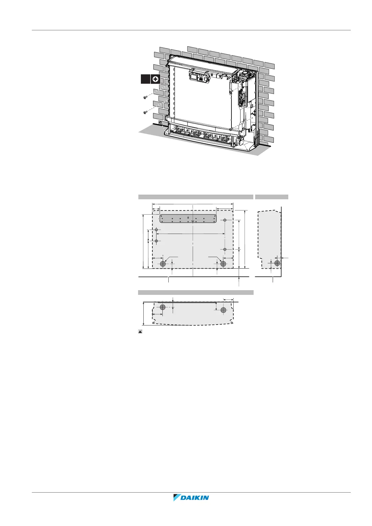
4 Secure the unit to the wall and floor using 6 screws M4×25L (field supply).
5 When the complete installation is finished, attach the front panel and the
front grille in their original position.
Wall-mounted installation
82
166
06≤
(mm)
627.5
750
006
553
300
200
285
115
238
b
b
b
b
75
06
75
45
Ø65
Ø65
45
d
e
75
75
54
h
g
54
45
f
A B
C
c c
a
6‒2 Indoor unit installation drawing: Wall-mounted installation
A Front view
B Side view
C Top view
a Mounting plate
b Screw hole 4×
c Floor
d Left-back piping hole location
e Right-back piping hole location
f Left/right piping hole location
g Left-bottom piping hole location
h Right-bottom piping hole location
6 Temporarily secure the mounting plate on the wall.
7 Make sure the mounting plate is level.
8 Mark the centres of the drilling points on the wall.
9 Secure the mounting plate on the wall using 5 screws M4×25L (field supply).
 Loading...