7 | Piping installation
Installer reference guide
41
CVXM-A, FVXM-A, CVXM-A9, FVXM-A9, FVXTM-A
Split system air conditioners
4P625991-1F – 2022.09
a Cut exactly at right angles.
b Remove burrs.
3 Remove the flare nut from the stop valve and put the flare nut on the pipe.
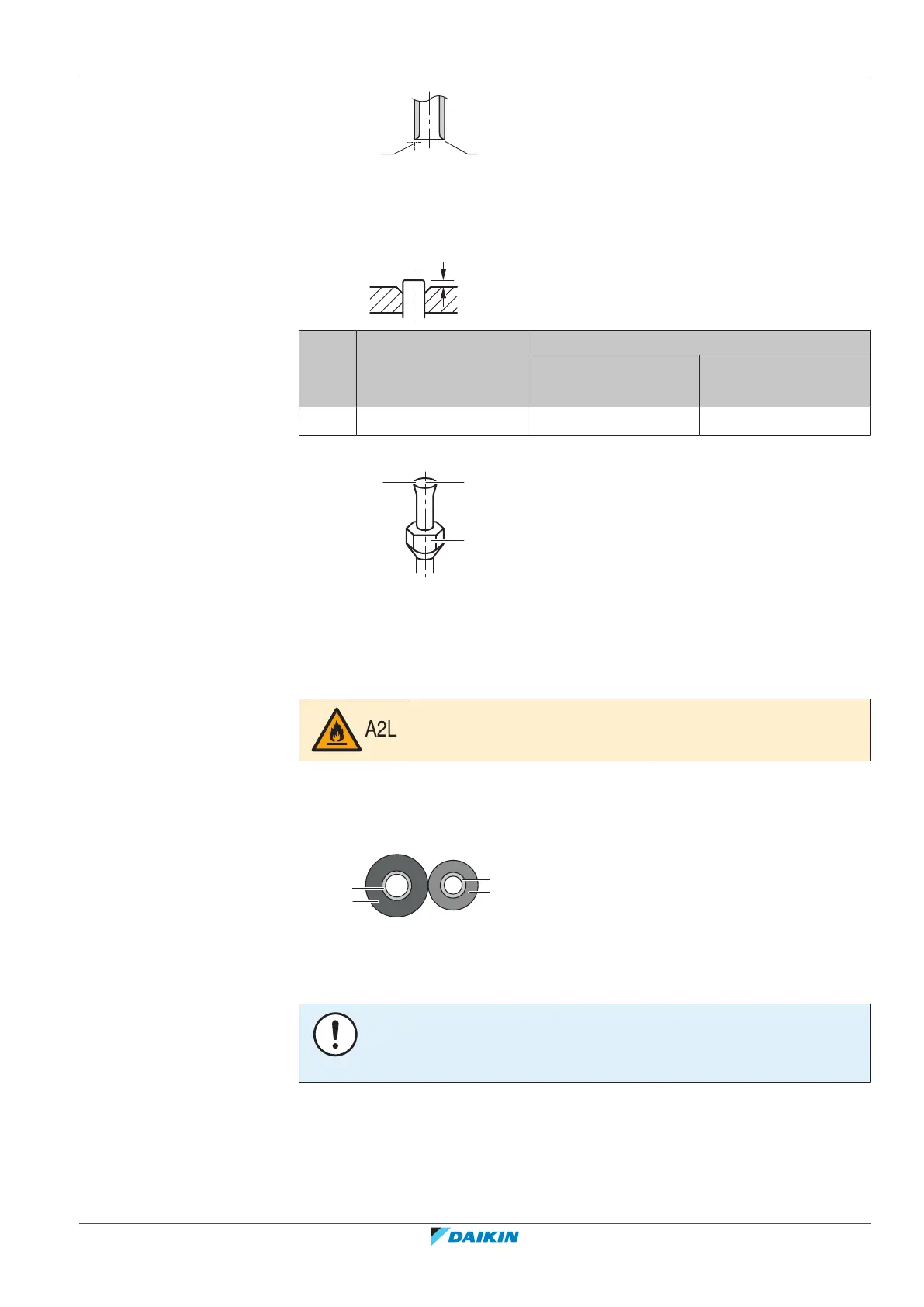
4 Flare the pipe. Set exactly at the position as shown in the following figure.
Flare tool for R32
(clutch type)
Conventional flare tool
Clutch type
(Ridgid-type)
Wing nut type
(Imperial-type)
A 0~0.5mm 1.0~1.5mm 1.5~2.0mm
5 Check that the flaring is properly made.
a Flare’s inner surface MUST be flawless.
b The pipe end MUST be evenly flared in a perfect circle.
c Make sure the flare nut is fitted.
7.2.6 To connect the refrigerant piping to the indoor unit
WARNING: MILDLY FLAMMABLE MATERIAL
The refrigerant inside this unit is mildly flammable.
▪ Pipe length. Keep refrigerant piping as short as possible.
1 Connect refrigerant piping to the unit using flare connections.
2 Insulate the refrigerant piping on the indoor unit as follows:
a Gas pipe
b Gas pipe insulation
c Liquid pipe
d Liquid pipe insulation
NOTICE
Make sure to insulate all refrigerant piping. Any exposed piping might cause
condensation.
3 Close the slit on the refrigerant pipe connection and secure it with a tape
(field supply). Make sure there are no gaps.
4 Wrap the slit and the end of the insulation of the connected refrigerant piping
with insulation piece (accessory). Make sure there are no gaps.
 Loading...