6 | Unit installation
Installer reference guide
31
CVXM-A, FVXM-A, CVXM-A9, FVXM-A9, FVXTM-A
Split system air conditioners
4P625991-1F – 2022.09
16 When the complete installation is finished, attach the front panel and the
front grille in their original position.
Half-concealed installation
5
4
30
f
734~740
170
350
70
200
593~595
170 350
d e
c
c
a
A B
(mm)
a
a
75
54
Ø60
Ø60
54
75
C
159
238
689
159
b b
06
75
75
54
h
g
627.5
115
285
b
b
b
b
300
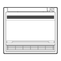
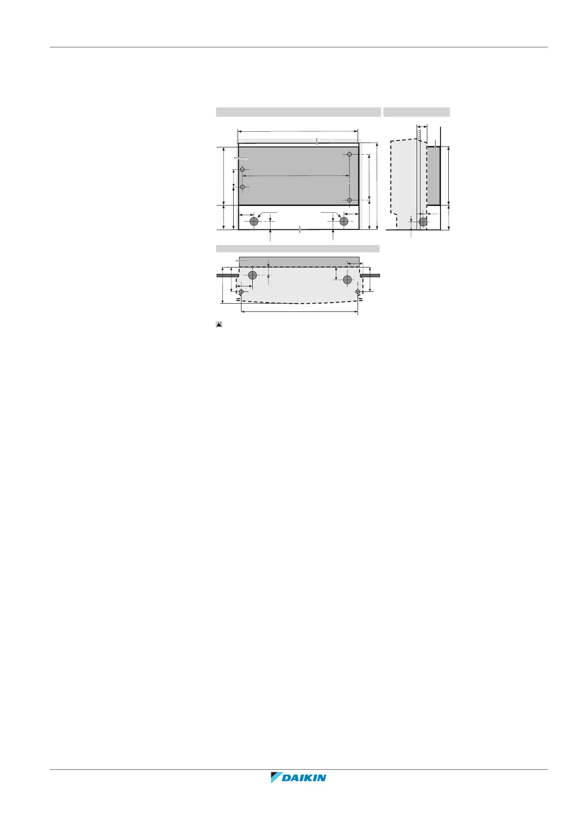
6‒3 Indoor unit installation drawing: Half-concealed installation
A Front view
B Side view
C Top view
a Extra filler board
b Screw hole 6×
c Hole
d Left-back piping hole location
e Right-back piping hole location
f Right/left piping hole location
g Left-bottom piping hole location
h Right-bottom piping hole location
17 Make a hole in the wall as illustrated above.
18 Install the extra filler board (field supply) in accordance with the space
between the unit and the wall. Make sure there is no gap between the unit
and the wall.
19 Drill a wall hole, depending on which side piping is taken out. See "6.3.2 To
drill a wall hole"[432].
20 Remove the slit portions using nippers. See "6.3.3 To remove the slit
portions"[432].
21 Open the front panel, remove the front grille, remove the top and side
casings.
22 Secure the unit to the extra filler board and to the floor using 6 screws
M4×25L (field supply).
 Loading...