baCneT ConfIguraTIon and CommIssIonIng
www.DaikinApplied.com 53 ED 15103-6 • MICROTECH III WSHP UNIT CONTROLLER
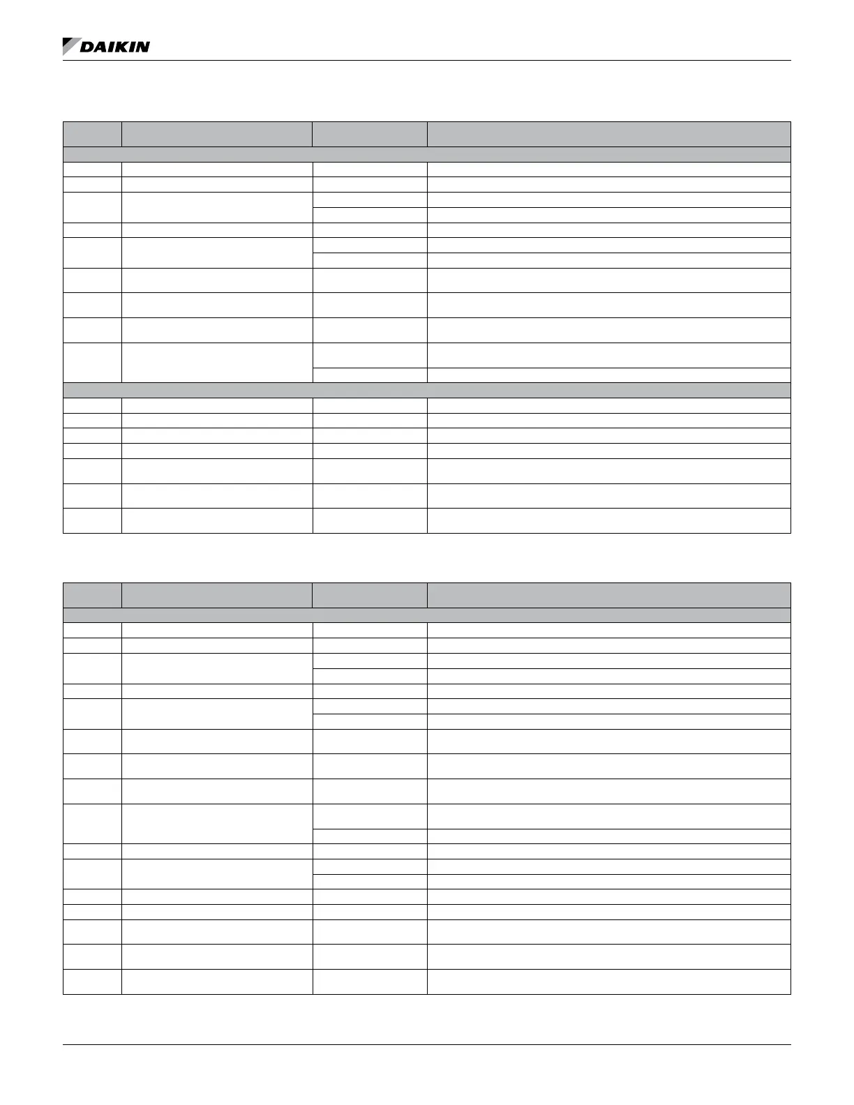
Table 25: Bit Description for SmartSource Single and Two Stage Compressor (Models GSH/GSV, GTH/GTV and GCV)
Bit
Number
Bit Description Setting Description
Unit Controller Jumpers
0 Compressor ON (1) Compressor request
1 Fan Main ON (1) Fan Main request
2 Reversing Valve
ON (1) Heating position for compressor
OFF (0) Cooling position for compressor
3 Pump Request / Isolation Valve ON (1) Water ow Is required
4 Alarm Output (A – Terminal)
ON (1) Alarm output is energized with 24VAC when there is a fault
OFF (0) Alarm output is de-energized when there is no fault
5 Remote Circuit #1 – Red LED OFF (0) / ON (1)
Red, Green, and Yellow LEDs are used in combination to indicate the unit
controller Fault/Status mode for Circuit #1
6 Remote Circuit #1 – Green LED OFF (0) / ON (1)
Red, Green, and Yellow LEDs are used in combination to indicate the unit
controller Fault/Status mode for Circuit #1
7 Remote Circuit #1 –Yellow LED OFF (0) / ON (1)
Red, Green, and Yellow LEDs are used in combination to indicate the unit
controller Fault/Status mode for Circuit #1
8 Room Sensor Status LED
ON (1)
Indicates the Room Sensor Status LED is ON steady. LED is ON when the unit
controller is in either the Occupied or Bypass modes
OFF (0) Indicates the Room Sensor Status LED is either ashing or constantly OFF
I/O Expansion Module Outputs
9 Compressor – High Stage Capacity ON (1) Compressor – High Stage Capacity request
10 Auxiliary Heat Stage #1 ON (1) Auxiliary Heat Stage #1 ON request
11 HGR/Waterside Economizer ON (1) HGR/Waterside Economizer request
12 Auxiliary Heat Stage #2 ON (1) Auxiliary Heat Stage #2 ON request
13 Remote Circuit #2 – Red LED OFF (0) / ON (1)
Red, Green, and Yellow LEDs are used in combination to indicate the unit
controller Fault/Status mode for Circuit #2
14 Remote Circuit #2 – Green LED OFF (0) / ON (1)
Red, Green, and Yellow LEDs are used in combination to indicate the unit
controller Fault/Status mode for Circuit #2
15 (MSB)
1
Remote Circuit #2 –Yellow LED OFF (0) / ON (1)
Red, Green, and Yellow LEDs are used in combination to indicate the unit
controller Fault/Status mode for Circuit #2
1. MSB = Most Signicant Bit
Table 26: Bit Description for Ennity Large Two Compressor (Models CCH/CCW and LVC/LVW)
Bit
Number
Bit Description Setting Description
Unit Controller Jumpers
0 Compressor #1 ON (1) Compressor #1 request
1 Fan Main ON (1) Fan Main request
2 Reversing Valve #1
ON (1) Heating position for compressor #1
OFF (0) Cooling position for compressor #1
3 Pump Request/Isolation Valve ON (1) Water ow is required
4 Alarm Output (A – Terminal)
ON (1) Alarm output is energized with 24VAC when there is a fault
OFF (0) Alarm output is de-energized when there is no fault
5 Remote Circuit #1 – Red LED OFF (0) / ON (1)
Red, Green, and Yellow LEDs are used in combination to indicate the unit
controller Fault/Status mode for Circuit #1
6 Remote Circuit #1 – Green LED OFF (0) / ON (1)
Red, Green, and Yellow LEDs are used in combination to indicate the unit
controller Fault/Status mode for Circuit #1
7 Remote Circuit #1 –Yellow LED OFF (0) / ON (1)
Red, Green, and Yellow LEDs are used in combination to indicate the unit
controller Fault/Status mode for Circuit #1
8 Room Sensor Status LED
ON (1)
Indicates the room sensor Status LED is ON steady. LED is ON when the unit
controller is in either the Occupied or Bypass modes
OFF (0) Indicates the room sensor Status LED is either ashing or constantly OFF
9 Compressor #2 ON (1) Compressor #2 request
10 Reversing Valve #2
ON (1) Heating position for compressor #2
OFF (0) Cooling position for compressor #2
11 HGR/Waterside Economizer ON (1) HGR/Waterside Economizer request
12 Electric Heat/Hydronic Heat ON (1) Electric Heat/Hydronic Heat ON request
13 Remote Circuit #2 – Red LED OFF (0) / ON (1)
Red, Green, and Yellow LEDs are used in combination to indicate the unit
controller Fault/Status mode for Circuit #2
14 Remote Circuit #2 – Green LED OFF (0) / ON (1)
Red, Green, and Yellow LEDs are used in combination to indicate the unit
controller Fault/Status mode for Circuit #2
15 (MSB)
1
Remote Circuit #2 –Yellow LED OFF (0) / ON (1)
Red, Green, and Yellow LEDs are used in combination to indicate the unit
controller Fault/Status mode for Circuit #2
1. MSB = Most Signicant Bit
baCneT ConfIguraTIon and CommIssIonIng

 Loading...


