OM 920-6 • MICROTECH UNIT CONTROLLER 136 www.DaikinApplied.com
operaTor’s guIde
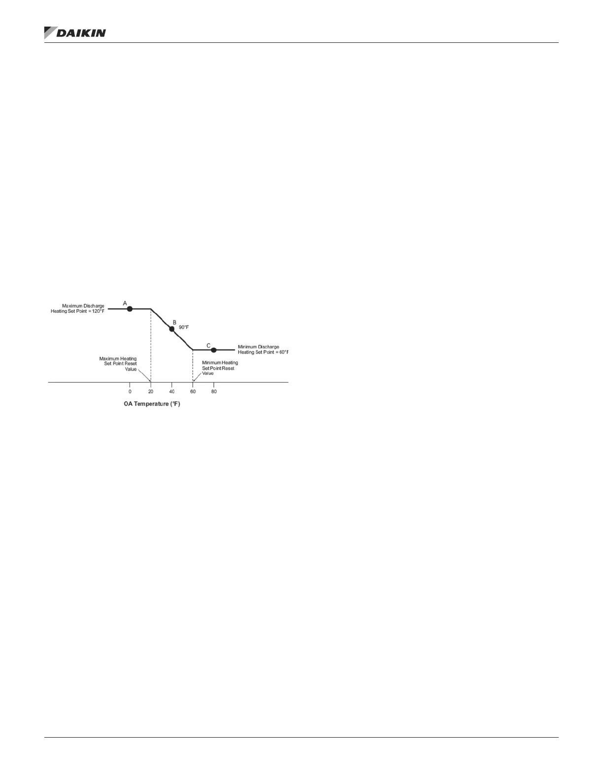
An example of discharge temperature reset based on outdoor
air temperature is illustrated in Figure 28 (Cooling Reset Type
Flag is set to “OAT” in this example). When the current outdoor
air temperature is greater than or equal to the Minimum
Cooling Set Point Reset Value (90°F in this example), the
Discharge Cooling Set Point is set equal to the Minimum
Discharge Cooling Set Point (55°F in this example). This is
shown as Point C in Figure 28. When the current outdoor air
temperature is less than or equal to the Maximum Cooling
Set Point Reset Value (70°F in this example), the Discharge
Cooling Set Point is set equal to the Maximum Discharge
Cooling Set Point (65°F in this example). This is shown as
Point A in Figure 28. When the current outdoor air temperature
is between the Minimum Cooling Set Point Reset Value and
the Maximum Cooling Set Point Reset Value, the Discharge
Cooling Set Point varies linearly between the Minimum
Discharge Cooling Set Point and Maximum Discharge Cooling
Set Point. This is shown as Point B in Figure 28.
Figure 28: Discharge Temperature Reset Based on
Temperature
Indoor Air Fan - ON/OFF Control
A supply fan is provided on every unit. That may be the only
fan, but either a return fan or an exhaust fan, or fans, can
be provided also. The start/stop signal and the speed signal
for fans that are controlled by variable frequency drives are
provided via an internal ModBus network. Constant volume
supply and return fans are started and stopped through digital
outputs.
Supply Fan
The supply fan is turned ON when the unit enters the
Recirculation state. The supply fan is turned OFF when
the unit transitions to the OFF state, but it stays on for a
OffHtClDelayTime (Default- 120 seconds) if the unit is turned
OFF while DX cooling or staged heating is active. The
OffHtClDelayTime function is overridden when and Emergency
Off or Duct High Limit fault is active.
Return Fan
A return fan driven by a variable frequency drive is started
four seconds after the supply fan is started to reduce the amp
draw peak on startup. A constant volume return fan is turned
ON through the same output as the supply fan. An external
Fan Delay Relay is used to provide a delay between startups
if required.
Supply Fan Capacity Control (VAV)
The speed of a modulating supply fan is controlled by a
0-100% signal provided to the VFD via an internal Modbus
network. Supply Fan Capacity Control for a modulating fan
is controlled to either maintain the duct static pressure at a
desired value or maintain a xed speed based on a signal
provided via a network.
The choice of control method, SF Cap Ctrl, may be set to
Duct Pressure or Speed via the keypad. After the supply fan is
started, a speed signal of 33% is sent to the variable frequency
drive for the DSPCtrlDelay (Default=30 seconds). Control
reverts to either duct pressure or speed after the fan has been
on for the duration of the DSPCtrlDelay time. The VFD speed
is not controlled below the minimum SAF speed setting (default
33%) while the fan is operating.
NOTE: Units supplied with Daikin MD2, MD3, and MD6
drives will have a user editable maximum supply fan
hertz setpoint (default 60 Hz) located in the SAF Set
Up menu. This parameter can be changed when job
site conditions require the speed of the drive to be
above 60 Hz.
Duct Static Pressure Control
The supply air fan speed is controlled by a VFD. The control
parameter for the fan speed is the duct static pressure setpoint.
If the duct static pressure is below the duct static pressure
setpoint by more than ½ the deadband, the fan speed will
increase. Likewise if the duct static pressure is above the
duct static pressure setpoint by more than ½ the deadband
the fan speed will decrease. Example - if the duct static
pressure setpoint is 1.2" and the deadband is 0.1",the duct
static pressure must reach 1.14 before the fan will increase in
speed. The Duct Static Pressure setpoint may be set through
the keypad or via a network signal. The active setpoint is
changed whenever either of these values changes so it equals
whichever value was changed most recently.
Speed/Network
When speed control is selected, the fan operates at the larger
of its minimum speed or a value provided via a connected
network or the keypad/display.
Single Zone VAV Control (1ZnVAV)
When space temperature control is selected, the supply fan
VFD is controlled with a PI_Loop to maintain the Control
Temperature input at the Occupied or Unoccupied Cooling
Setpoint or Occupied or Unoccupied Heating Setpoint. This
control choice is designed for DAC control type and will be
used in applications where the unit will act as a single VAV box
to control space temperature. Cooling and heating discharge
air temperature control and outside air damper control will
function in the normal manner as with VAV units.

 Loading...


