SAF Set-up
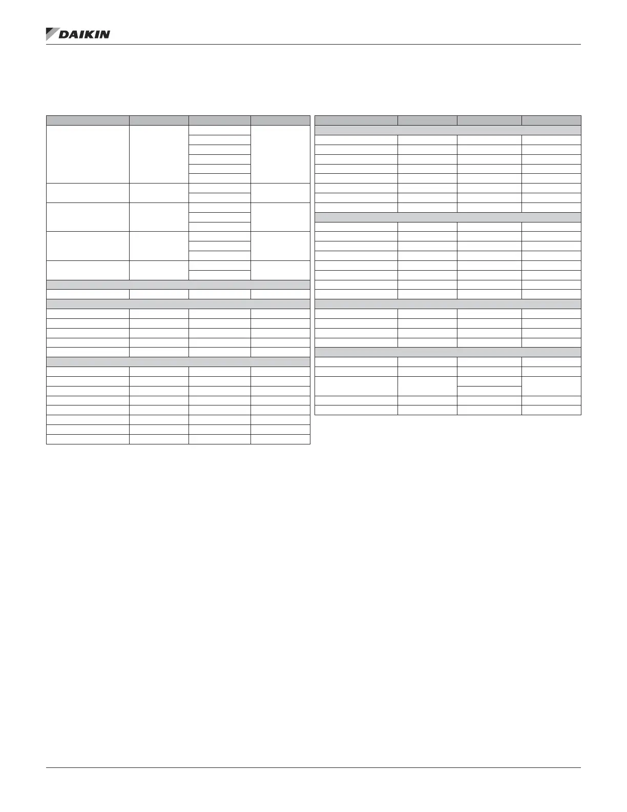
Table 21: Supply Fan Speed Menu
Item Display Name Default Setting Range Password Level
Item Display Name Default Setting Range Password Level
SAF Ctrl= DSP
DSP
4
CO
2
CONTROL
Spd/Net Min PPM= 0ppm 0–5000ppm 2
1ZnVAV Max PPM= 2000ppm 0–5000ppm 2
BSP V/A @ Min PPM= 0.0/V 0.0–20.0/V/mA 2
CO2 V/A @ Max PPM= 10.0/V 0.0–20.0/V/mA 2
CFM Min SAF PPM= 800 0–5000ppm 4
AplyInputChgs= No
No
2
Max SAF PPM= 1100 0–5000ppm 4
Yes Min PPM Spd= 50 0–100% 4
CO
2
Input= None
None
2
Max PPM Spd= 100 0–100% 4
VDC CFM CONTROL
MA Min CFM= 0CFM 0–60000CFM 2
CFM Input= None
None
2
Max CFM= 10000CFM 0–60000CFM 2
VDC V/A @Min CFM= 0.0/V 0.0–20.0/V/mA 2
MA V/A @Max CFM= 10.0/V 0.0–20.0/V/mA 2
BSP Input= No
No
2
SAF CFM DB= 3% 0–100% 4
Yes SAFCFM Period= 30s 0–999s 4
SPEED CONTROL SAF CFM Gain= 0.1 0.0–100.0 4
Rem SAF Cap= 33% 0–100% 4 SAF CFM MxChg= 5% 0–100% 4
DSP CONTROL BSP CONTROL
DSP DB= 0.1in 0–0.5in 4 BSP DB= 0.01in 0.0–0.1in 4
SAF Ramp Time= 60s 0–999s 4 BSP Period= 5s 0–999s 4
Min Period= 5s 0–999s 4 BSP Gain= 0.2 0.0–100.0s 4
Max Spd Chg= 15% 0–100% 4 Max Spd Chg= 4% 0–100% 4
DuctPress1= — 0.0–5.0in 2 SAF SETUP
1 ZONE VAV CONTROL SAF Ctrl Dly= 30s 0–999s 4
Min Clg Spd= 40% 0–100% 4 Min Speed= 33% 0–100% 4
Max Clg Spd= 100% 0–100% 4
VAVBox Out= —
Heat
2
Min Htg Spd= 40% 0–100% 4 Cool
Max Htg Spd= 100% 0–100% 4 MaxVentSpd= 100% 0–100% 2
Space Period= 60s 0–999s 4 Max SAF RPM= 2600 0–5000 2
Space Gain= 0.8 0.0–100.0s 4
Space PAT= 400s 0–999s 4
Space Max Chg= 10% 0–100% 4
SAF Ctrl is an adjustable parameter used to select how the
supply fan is to be controlled. The supply fan can normally be
controlled by duct pressure, space temperature (single zone
VAV or 1ZnVAV) or by a percentage of supply air fan speed
from 33% to 100%. On 100% OA unit applications the fan can
be controlled to maintain building static pressure, space carbon
dioxide level or and airow based on a eld supply airow
station. The speed option is typically used with a building
automation system. When single zone VAV control is selected,
the supply fan is controlled with a PI_Loop to maintain the
Control Temperature input at the Occupied Cooling Set Point or
Occupied Heating Set Point. When BSP is selected the supply
fan is controlled with a PI_Loop to maintain the building static
pressure at a building static pressure Set Point.
When CO
2
is selected the supply fan is controlled to maintain
the CO
2
ppm between adjustable limits by varying the supply
fan speed between an adjustable range. When CFM is
selected the supply fan is controlled with a PI_Loop to maintain
the measured CFM at a CFM set point.
AplyInputChgs is the Apply Input Changes ag must be
changed from no to yes in order for the controller to recognize
the changes. Setting the Apply Input Changes ag to YES will
automatically reset the controller.
CO
2
Input is an adjustable item used to select the type of
input for a eld installed CO
2
sensor. If this is set to None the
controller ignores any CO
2
sensor input. If CO
2
control and/
or monitoring is desired this parameter is set to VDC or mA
to match the input type of the eld supplied CO
2
sensor input.
This parameter applies only to 100% OA unit congurations.
CFM Input is an adjustable item used to select the type of
input for a eld installed airow station. If this is set to None the
controller ignores any eld airow station input. If CFM control
and/or monitoring is desired this parameter is set to VDC or mA
to match the input type of the eld supplied airow input. This
parameter applies only to 100% OA unit congurations.
Menu desCrIpTIons
www.DaikinApplied.com 35 OM 920-6 • MICROTECH UNIT CONTROLLER

 Loading...


