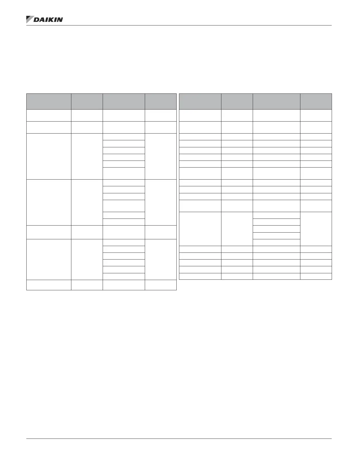
Network Input Status Menu
The Network Input Status Menu provides diagnostic
information to qualied service personnel. The items listed
in this menu will provide current status information of the
controller’s network inputs.
Table 44: Network Input Status Menu
Item Display Name
Default
Setting
Range
(No Network
value in Bold)
Password
Level
Item Display
Name
Default
Setting
Range
(No Network value
in Bold)
Password
Level
Net OAT In= —
-50.0–200.0°F
(621.8°F)
2 Net Cl Ena Vl= — 0–255% (255%) 2
Net SpaceT In= —
-0.0–150.0°F
(621.8°F)
2 Net Ht Ena Sw= — -1.0–1.0 (-1.0) 2
NetCurrState= —
Occ
2
Net Ht Ena Vl= — 0–255% (255%) 2
Unocc Net Ec Ena Sw= — -1.0–1.0 (-1.0) 2
TntOvrd Net Ec Ena Vl= — 0-255% (255%) 2
Standby Net SAF Cap= — 0–100% (164%) 2
Auto Net ExhF Cap= — 0–100% (164%) 2
(NULL) Net Space IAQ= —
0–5000ppm
(65535ppm)
2
NetNextState= —
Occ
2
Net Rel Humid= — 0-100% (164%) 2
Unocc Net DATClgSpt= — 40.0–100.0°F 2
TntOvrd Net DATHtgSpt= — 40.0–140.0°F 2
Standby nviSetpoint= —
0.0-100.0°F
(621.8°F)
2
Auto
OccManCmd= —
Occ
2
(NULL) Unocc
NetTmToNxtSt= —
0–65534min
(65535min)
2
TntOvrd
Standby
Net App Mode= —
Off
2
Auto
HeatOnly Net MinOA= — 0–100% 2
CoolOnly nvoEffSpt= — 0.0–100.0°F 2
FanOnly nciOccClgSpt= — 0.0–100.0°F 2
Auto nciOccHtgSpt= — 0.0–100.0°F 2
(Auto) nciHVACType= — HVT_GEN 2
Net Cl Ena Sw= — -1.0–1.0(-1.0) 2
OM 920-6 • MICROTECH UNIT CONTROLLER 66 www.DaikinApplied.com
Menu desCrIpTIons

 Loading...


