11
IM 1365-1
WWW.DAIKINAPPLIED.COM
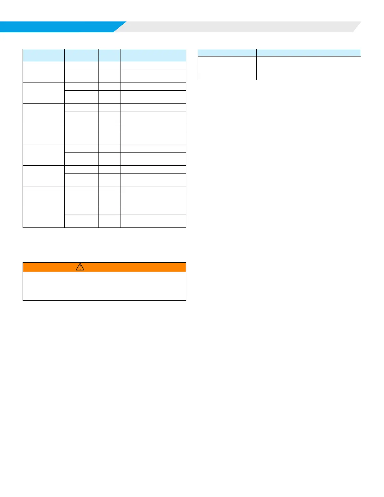
DISPLAy MODES
Table 11: Display Example
Sensor State Action
LED
Display
LED Display Interpretation
Normal operation
Initial Display
S01
Sensor #1
Button Press
024
Sensor #1
LFL=02.4%
There is an
active fault
condition
Button Press
S02
Sensor #2
Button Press
FLT
Sensor #2
Self-Test Failure
Normal operation
Button Press
S03
Sensor #3
Button Press
019
Sensor #3
LFL=01.9%
Normal operation
Button Press
S04
Sensor #4
Button Press
021
Sensor #4
LFL=2.1%
Not Installed
Button Press
S05
Sensor #5
Button Press
LOC
Sensor #5
Loss of Com
Not Installed
Button Press
S06
Sensor #6
Button Press
LOC
Sensor #6
Loss of Com
Not Installed
Button Press
S07
Sensor #7
Button Press
LOC
Sensor #7
Loss of Com
Not Installed
Button Press
S08
Sensor #8
Button Press
LOC
Sensor #8
Loss of Com
5. The display returns to normal operation upon the button
press after the last data is shown.
Manual Test Mode
WARNING
Placing the MT6210 into Manual Test Mode may initiate a system mitigation
response, including energizing fans, disabling compressors, or other unit
specic operational responses. Ensure unit is prepared for operation and
safety precautions are followed prior to entering Manual Test Mode.
Pressing and releasing the MODE button for more than 5
seconds but less than 10 seconds places the display into Manual
Test Mode. During this time interval, the display shows TST.
Function
The user can place the MT6210 into an alarm state to test
system response in a eld installation. The test mode will last for
ve (5) minutes, then return to normal operation.
Display
The display indicates the test mode is active and a countdown
timer showing the time remaining (seconds) in the Manual Test
Mode, as shown in Table 12.
Table 12: Display Example
LED Display LED Display Interpretation
A99 Field Test Mode Indication
TST Test Indication
300 5 Minute Countdown Timer
GID Display Mode
Pressing and releasing the MODE button for more than 10
seconds but less than 15 seconds places the display into GID
Display Mode. During this time interval, the display shows GID.
Function
The user can place the MT6210 into GID Display Mode to
view the current values for all active parameters in the Global
Identiers List. This mode is only available when the control is in
the RUN state (no faults/alarms).
Display
The display automatically scrolls through all active GIDs
sequentially. The following rules apply:
1. The display will show the GID number (sequentially
beginning with GID #1) followed by the current value for
that GID as shown in Table 13 on page 12.
2. Each sensor address is displayed, whether the sensor is
installed or not.
3. For each valid sensor (address ≠ “0”), the control displays
the sensor information, including:
— Sensor address
— LFL level
— Sensor state
— Sensor faults
— Sensor temperature
— Sensor humidity
— Sensor pressure (future feature, will show invalid)
4. If a sensor is not communicating at the time of display, the
sensor address GID will show a zero (0) and the details of
that sensor will not be shown.
5. If a GID value is greater than “999” or not valid, the LED
will be blank during that GID value display time.