SEQUENCE OF OPERATION
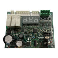
MT6210 A2L MITIGATION CONTROLDAIKIN APPLIED
8
Sequence of Operation
Power-Up
At power-up, the MT6210 initiates the microprocessor and then
begins establishing the two Modbus communication networks.
This process involves the following activities:
• Sensor discovery:
The control sends requests on the Modbus client network to
sensors 1 through 8 to identify the number and addresses
of all sensors available on the network.
• Unit controller requests:
The control listens on the Modbus server network for
communications from a unit controller (if present). Unit
controller communications are not necessary for operation.
• If a unit controller is present and communicating, the
number of required sensors for the system is sent to
the MT6210, which stores this parameter. Otherwise,
the MT6210 will use the default number of sensors
programmed into its memory.
The power-up process takes approximately 30 seconds to
complete, after which time the control will display the network
summary as shown in Table 2.
Table 2: Power-Up Display
LED
Display
LED Display
Interpretation
Description Range
St
UP
System Start-Up
30 second power-up se-
quence: initiates the two
Modbus networks, allows
time for sensor warm-up
N/A
NS
=N
Number of Sensors
Indicates the expected
number of A2L sensors
(N) for the application
1 … 8
S1
=1 or 0
Sensor #1 Status
Indicates Modbus
communication with A2L
sensor #1
0=None
1=Present
SN
=1 or 0
Sensor #N Status
Indicates Modbus
communication with A2L
sensor #N (N = 2…8)
(Status is shown for all 8
sensors)
0=None
1=Present
UC
=1 or 0
Unit Control Mod-
bus Status
Indicates Modbus com-
munication with the unit
controller
0=None
1=Present
Run
Once the power-up sequence is complete, the MT6210 enters a
normal run state. During the run state, the control monitors the
Modbus networks and maintains the digital and binary outputs
while executing the following specic activities:
1. Veries that the number of discovered sensors matches the
expected number for the specic system in which installed.
2. Veries the addresses for all sensors are sequential,
starting with “S01” and proceeding to “SN”, where “N” is
the expected number of sensors, e.g. if N=3 for the system,
then discovered sensors would be “S01”, S02”, and “S03”.
3. Monitors the status of each individual refrigerant sensors,
including the sensor status and %LFL detection level.
4. Monitors any requests from a unit controller (if present
on the server Modbus network) and responds with the
information requested.
5. Displays system status via the three seven-segment LEDs
mounted on the board.
Table 3: Run Indication
Display Indication
run
Normal Operation
(No Alarms, No Faults)
6. Responds to any button presses detected on the MODE
button.
Alarm - Active Refrigerant Leak
Detected
The MT6210 continuously monitors each refrigerant sensor’s
reported %LFL level via the client Modbus network. If any sensor
reports a %LFL level above 15%, a refrigerant leak condition
exists, and the control enters an “Alarm” condition.
The control executes the following actions when a leak event has
been detected:
1. The Alarm relays are de-energized opening the Alarm relay
contacts.
2. The Customer relay is energized closing the Customer
relay contacts.
3. The Alarm binary output changes state from 5VDC (normal)
to 0VDC (Alarm).
4. The Modbus state parameter is changed to indicate an
alarm condition that will be reported to a unit controller
requesting this information.
5. The diagnostic LEDs display the Alarm condition as shown
in Table 4.