9
IM 1365-1
WWW.DAIKINAPPLIED.COM
SEQUENCE OF OPERATION
Table 4: Alarm Indications
Display Indication
A0N
LFL
251
Alarm - Sensor #N
Lower Flammability Limit
LFL % - Sensor #N (xx.x)
6. The control continues to monitor the sensors in the network
and maintains the alarm condition until all sensors are
indicating less than 15% LFL.
7. Once all LFL levels fall below 15%, the control maintains
the alarm condition for an additional 5 minutes. During this
5-minute period, the display will indicate a timer countdown
as shown in Table 5.
Table 5: Alarm/Timer Indications
Display Indication
A0N
LFL
010
300
Alarm - Sensor #N
Lower Flammability Limit
LFL % - Sensor #N (xx.x)
5-minute timer (seconds)
8. Once the 5-minute timer has expired and all LFL remain
below 15%, the control returns to a normal RUN mode,
de-energizing all relays and digital outputs and setting the
Modbus state parameter back to normal.
Fault - Abnormal System Operation
The MT6210 continuously monitors the refrigerant detection
system to ensure all elements of the system are operating
properly. If any abnormality other than a leak detection, the
control enters a Fault condition. A Fault condition can be caused
by a number of system issues:
• Sensor Conguration: CfG
A mismatch between the expected number of sensors and
the actual number of communicating sensors.
• Loss of Communications: LOC
Modbus failure with a discovered sensor.
• Sensor Self-Test Error: FLT
A sensor has reported a self-test error. Each sensor runs
internal diagnostics to verify the calibration and proper
functioning of the sensing element, and reports that status
of this self-test over the Modbus network to the MT6210.
If any of these fault conditions are detected, the control enters a
“Fault” condition. The control executes the following actions when
a fault event has been detected:
1. The Fault binary output changes state from 5VDC (normal)
to 0VDC (Fault).
2. The Modbus state parameter is changed to indicate a fault
condition that will be reported to a unit controller requesting
this information.
3. The diagnostic LEDs display the various fault conditions as
shown in Table 2.
Table 6: Fault Descriptions
LED
Display
LED Display
Interpretation
Description
FLT
CF6
Sensor Conguration
Error
The sensors identied during the
discovery process do not match
the expected conguration.
F01
LOC
Fault Sensor #1
Loss of Communi-
cations
A Fault condition exists due to a
loss of Modbus communications
with sensor #1.
F0N
LOC
Fault Sensor #N
Loss of Communi-
cations
A Fault condition exists due to a
loss of Modbus communications
with sensor #N.
N=relative sensor number (1-8)
F01
FLT
Fault Sensor #1
Self-Test Error
A Fault condition exists based on
a sensor #1 failure during the self-
test process.
F0N
FLT
Fault Sensor #N
Self-Test Error
A Fault condition exists based on
a sensor #N failure during the self-
test process.
N=relative sensor number (1-8)
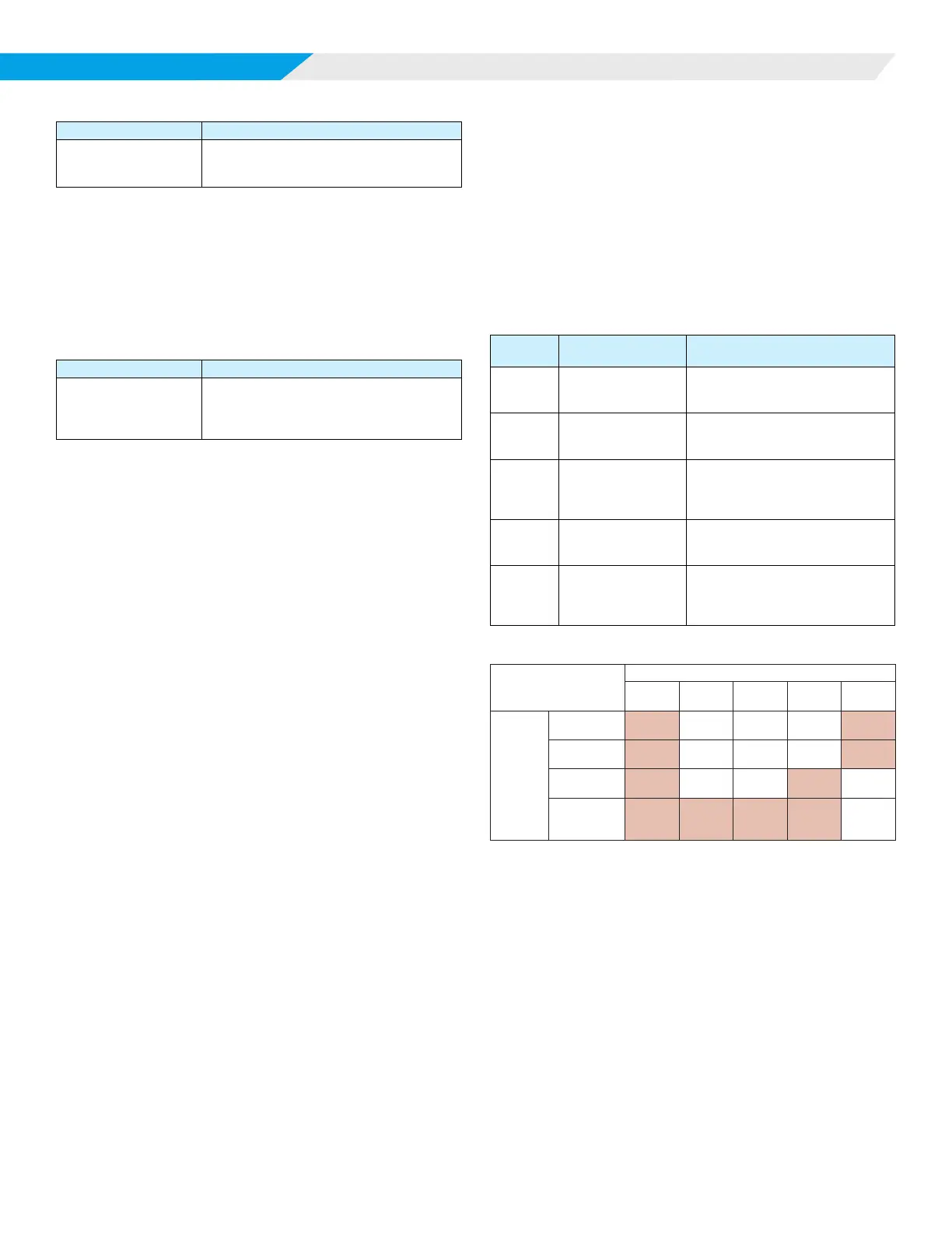
Table 7: MT6210 A2L Control Board State Matrix
MT6210 A2L Control
Board State Matrix
Board States
No
Power
Start-up Run Fault Alarm
Outputs
Alarm
Relay
Open Closed Closed Closed Open
Alarm Digital
Output
Low High High High Low
Fault Digital
Output
Low High High Low High
Customer
Connection
Relay
Open Open Open Open Closed
NOTE 1: If a leak is detected, the relay for the supply air fan will energize or de-
energize depending on conditions shown in this table.
NOTE 2: Shaded cells represent de-engergized relays (O).
Non-shaded cells represent energized relays (On).