CONNECTIONS
MT6210 A2L MITIGATION CONTROLDAIKIN APPLIED
6
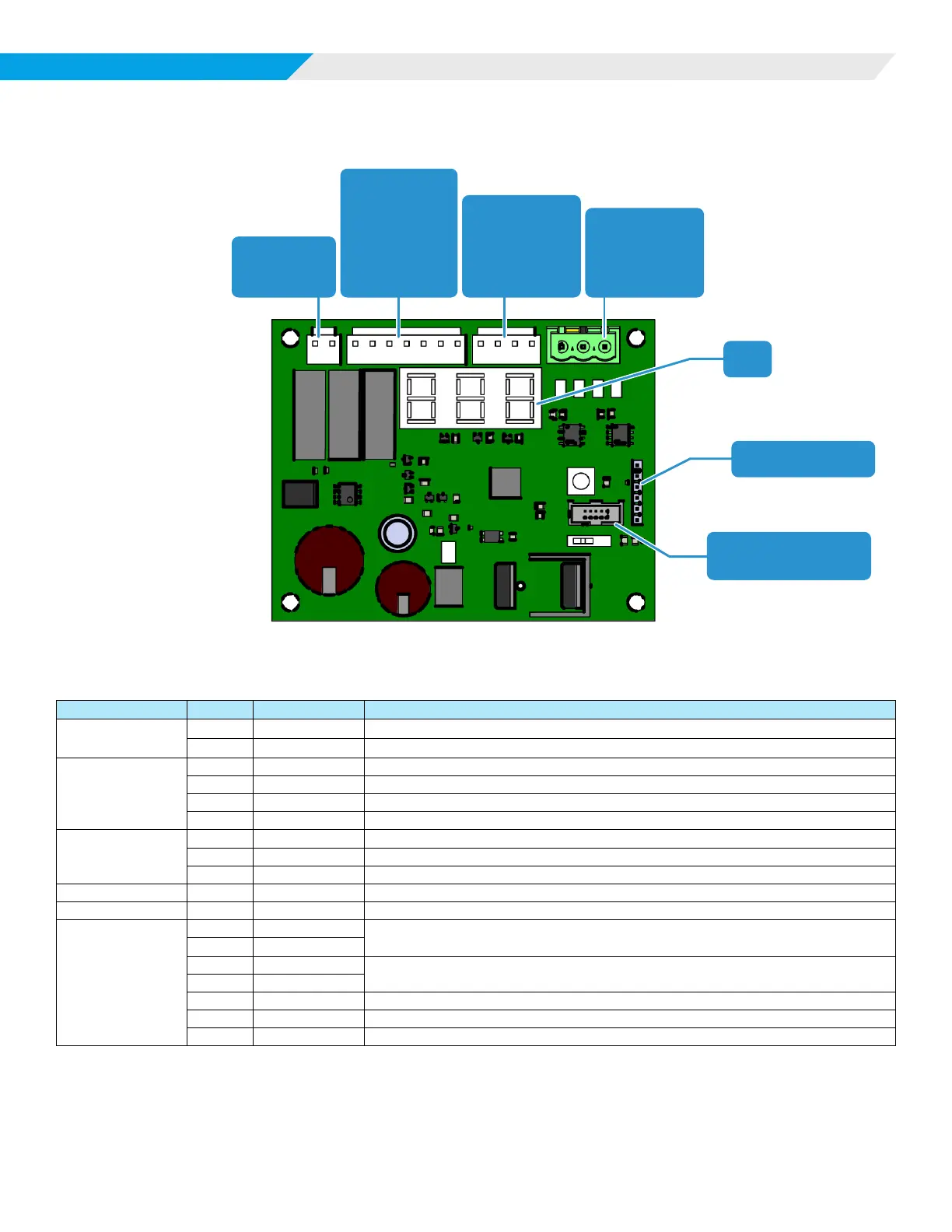
Connections
Figure 1: Board Layout
JTAG Interface Port
(Factory Use Only)
H4 – Service Port
LED
H3 – Modbus
(Server–UC)
1. B
2. A
3. GND
H2 – Modbus
(Client–Sensor)
1. GND
2. A
3. B
4. 5V
H2 – Power
1. 24 VAC
2. GND
H6 – Outputs
1. C1ALM
2. ALM
3. C2CUST
4. CUST
5. FLT_S
6. ALM_S
7. GND
Table 1: MT6210 Connections
Connector Pin Label Description
H1
Power
1 24 VAC 24 VAC Control Power from Transformer
2 GND Common / Chassis ground
H2
Modbus Client
1 GND Common - Sensor Power
2 A Modbus Communications to Refrigerant Sensors
3 B Modbus Communications to Refrigerant Sensors
4 5V 5VDC - Sensor Power
H3
Modbus Server
1 B Modbus Communications to Unit Controller
2 A Modbus Communications to Unit Controller
3 GND Common
H4 1-6 Various Service Port - for programming using the appropriate USB interface cable
JTAG1 1-10 None Factory Use Only
H6
Outputs
1 C1ALM
Alarm Dry Contacts – Activates for Alarm or Fault
2 ALM
3 C2CUST
Customer Dry Contacts – Activates for Alarm or Fault
4 CUST
5 FLT_S Fault Digital Output - System fault
6 ALM_S Alarm Digital Output - Leak Event
7 GND Common / Chassis ground