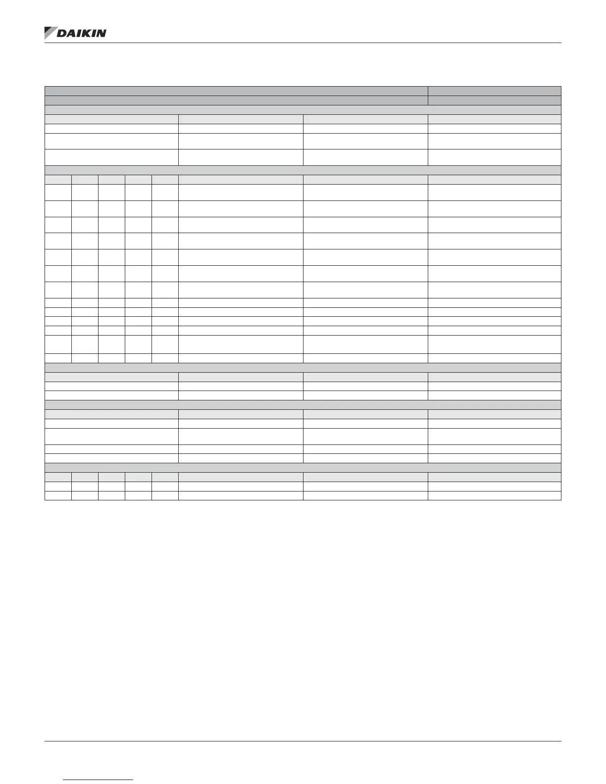
Table 12: DPS/DPH Expansion Module D I/O
I/O Cong. Code Condition
Expansion Module D Pos. 1=3or4
Analog Inputs — NTC
# Point Comments Cong. Code Condition
AI 1 Indoor Refrigerant Temperature (IRT) 10K Thermistor (STD) 1 = 4 & 30 = 3, 4, 5 or 6
AI 2
Outdoor Refrigerant Temperature
(ORT)
10K Thermistor (STD) 1 = 4 & 30 = 3, 4, 5 or 6
AI 3
Outdoor Coil Defrost Temperature
(DFT)
10K Thermistor (STD) 1 = 4 & 30 = 3, 4, 5 or 6
Universal Inputs/Outputs
# DI AI DO AO Point Comments Cong. Code Condition
X 1 X
Compressor Suction Pressure Sensor
(PTS)
0.5–4.5 VDC 0–350 psi
X 2 X
Compressor Discharge Pressure
Sensor (PTD)
0.5–4.5 VDC 0–700 psi
X 3 X
INV Compressor Discharge Line
Refrigerant Temperature (DRT1)
100K Thermistor (HT)
X 4 X
STD3 Compressor Discharge Line
Refrigerant Temperature (DRT3)
100K Thermistor (HT) 4 = M
X 5 X Heating Valve
Gas 2–10 VDC HW/STM 2–10 VDC
SCR 0–10 VDC
10 = 5, 6 or 7
X 6 X
Compressor Suction Line Refrigerant
Temperature (SRT)
10K Thermistor (STD)
X 7 X
Outdoor Coil Defrost Temperature
(DFT)
10K Thermistor (STD) 1 = 4 & 30 = 1 or 2
X 7 X INV Compressor Body Temperature 100K Thermistor (HT) 24, 25, 26 = 0, 1, 5
X 8 X Reheat Output 0–10 VDC 28 = 2
X 9 X Supply Temp Leaving Wheel 10K Thermistor (STD) 20 > 0 & 30 = 3, 4, 5 or 6
X 10 X Exhaust Temp Leaving Wheel 10K Thermistor (STD) 20 > 0 & 30 = 3, 4, 5 or 6
X 11 X OA Flow 0–10 VDC or 4–20 mA
8 = 1, 2, 3, 5,6 or 7 & 9 = 6 &
30 = 3, 4, 5 or 6
X 12 X Freezestat Switch 0-5 VDC 10 =5 & 8 = 8 or 9 & 30 = 3, 4, 5 or 6
Digital Input — 115V-230V
# Point Comments Cong. Code Condition
DI Freezestat Switch 115 VAC Input 10 = 5 & 8 = 3 or 6
DI OAD End Switch Input 115 VAC Input 8 = 8 or 9
Digital Outputs — Relay (SPST, Normally Open, 230 VAC 3 Amp)
# Point Comments Cong. Code Condition
DO 1 INV Board Power Up
DO 2
Refrigerant Receiver Gas Line
Solenoid Valve (SVR)
1 = 4
DO 3 Bypass Solenoid Valve (SVB)
DO 4 4 Way Reversing Valve (4WV) 1 = 4
Digital Outputs — Triac (24 VAC, 0.5 Amp)
# Point Comments Cong. Code Condition
DO 5 Bypass Damper CLOSED Energy Recovery 20 > 0 & 8 = 3 or 6 & 30 = 3, 4, 5 or 6
DO 6 Bypass Damper OPEN Energy Recovery 20 > 0 & 8 = 3 or 6 & 30 = 3, 4, 5 or 6
IM 919-3 • MICROTECH III CONTROLLER 22 www.DaikinApplied.com
ConTroller InpuTs/ouTpuTs