Removal of PCBs / Electrical Box Si00-876
12 Removal Procedure
2
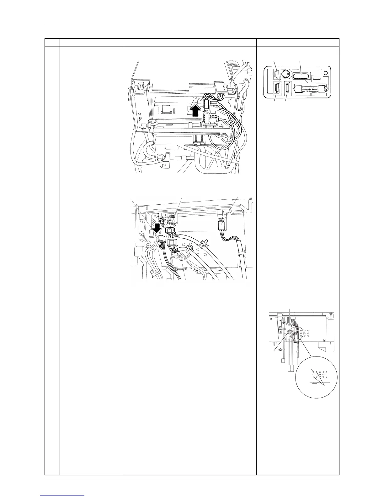
Disconnect the
harnesses from the
power supply PCB.
power supply PCB
[HL] (black): terminal board
[HE2] (yellow/green): earth
[HAC1] (black): main PCB
(AC1)
[HE1] (yellow/green): main PCB
(E)
3
Disconnect the
connectors of the front
side.
[S20]: electronic expansion
valve
[S40]: overload protector
[S80]: four way valve coil
[S90]: thermistors
The cooling only models do
not have the harness for
[S80].
When reassembling, insert
each clamp into the holes.
When reassembling, the
thermistor harness should
be placed between the
electrical box and the
reactor harness as below.
Step Procedure Points
(R2706)
HE1 V3 (varistor)
HE2 HL
(R17032)
[S40]
[S20] [S80]
[S90]
(R19135)
Reactor
harness
Thermistor
ASSY
(R17093)
Reactor harness
Thermistor
ASSY