5Technicaldata
Installationmanual
11
AZQS100~140B8V1B+AZQS100~140B7Y1B
Splitsystemairconditioners
4P3855281–2014.08
F1U~F8U
(AZQS125+140_V1)
▪ F1U~F4U:Fuse
▪ F6U:Fuse(T5.0A/250V)
▪ F7U,F8U:Fuse(F1.0A/250V)
F1U~F8U
(AZQS_Y1)
▪ F1U,F2U:Fuse(31.5A/250V)
▪ F1U(A2P):Fuse(T5.0A/250V)
▪ F3U~F6U:Fuse(T6.3A/250V)
▪ F7U,F8U:Fuse(F1.0A/250V)
H1P~H7P Lightemittingdiode(servicemonitoris
orange)
HAP Lightemittingdiode(servicemonitoris
green)
K1M,K11M Magneticcontactor
K1R
(AZQS_V1)
Magneticrelay(Y1S)
K1R
(AZQS_Y1)
▪ K1R(A1P):Magneticrelay(Y1S)
▪ K1R(A2P):Magneticrelay
K2R
(AZQS100_V1)
Magneticrelay
K2R
(AZQS_Y1)
▪ K2R (A1P): Magnetic relay (E1H
option)
▪ K2R(A2P):Magneticrelay
K10R,K13R~K15R Magneticrelay
K4R MagneticrelayE1H(option)
L1R~L3R Reactor
M1C Motor(compressor)
M1F Motor(upperfan)
M2F Motor(lowerfan)
PS Switchingpowersupply
Q1DI Earthleakagecircuitbreaker(field
supply)
R1~R6 Resistor
R1T Thermistor(air)
R2T Thermistor(discharge)
R3T Thermistor(suction)
R4T Thermistor(heatexchanger)
R5T Thermistor(heatexchangermiddle)
R6T Thermistor(liquid)
R7T
(AZQS125+140_V1)
Thermistor(fin)
R7T,R8T
(AZQS100_V1)
Thermistor(PositiveTemperature
Coefficient)
R10T
(AZQS_Y1)
Thermistor(fin)
RC Signalreceivercircuit
S1PH Highpressureswitch
S1PL Lowpressureswitch
TC Signaltransmissioncircuit
V1D~V4D Diode
V1R IGBTpowermodule
V2R,V3R Diodemodule
V1T~V3T Insulatedgatebipolartransistor(IGBT)
X6A Connector(option)
X1M Terminalstrip
Y1E Electronicexpansionvalve
Y1S Solenoidvalve(4wayvalve)
Z1C~Z6C Noisefilter(ferritecore)
Z1F~Z6F Noisefilter
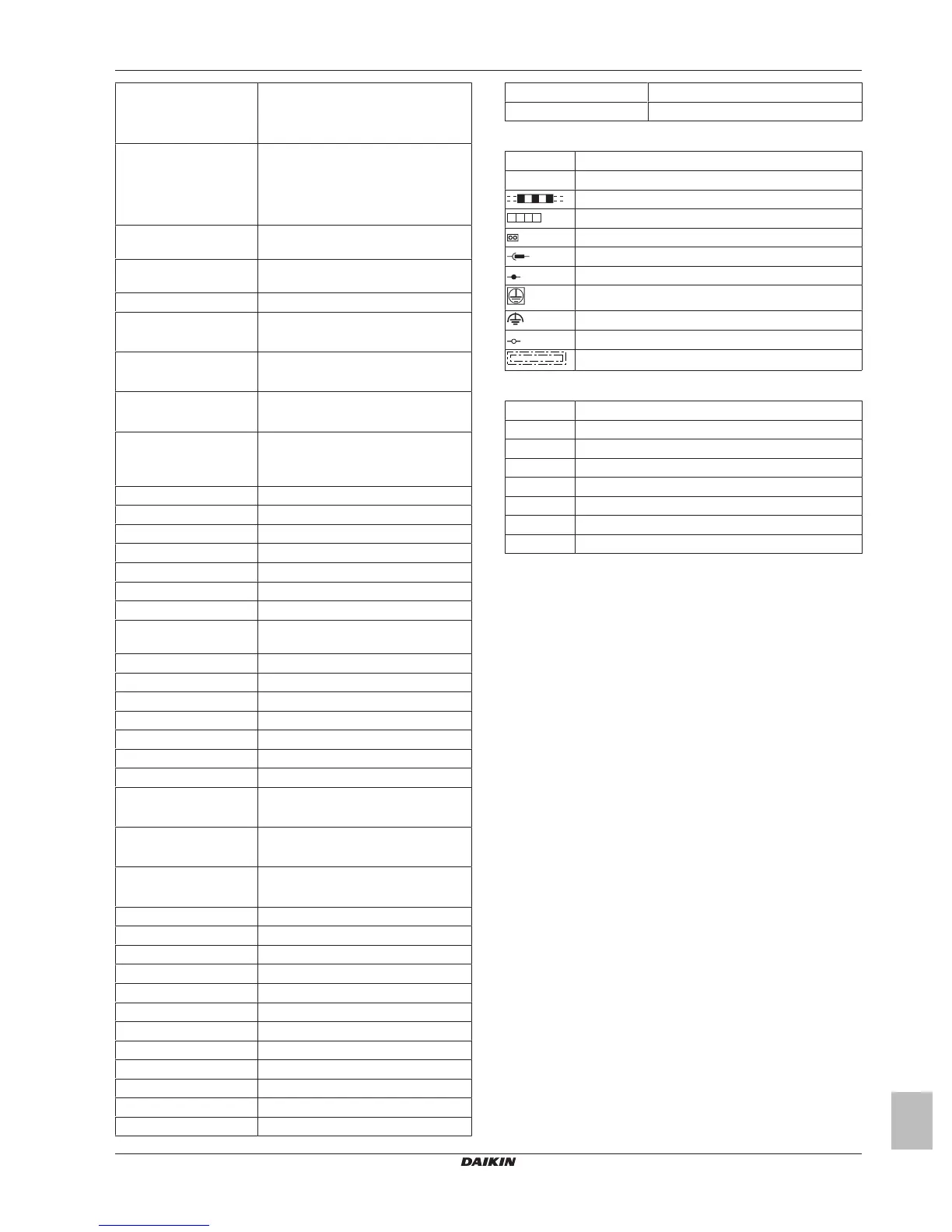
Symbols:
L Live
N Neutral
Fieldwiring
Terminalstrip
Connector
Relayconnector
Connection
Protectiveearth
Noiselessearth
Terminal
Option
Colours:
BLK Black
BLU Blue
BRN Brown
GRN Green
ORG Orange
RED Red
WHT White
YLW Yellow