3Installation
Installationmanual
8
AZQS100~140B8V1B+AZQS100~140B7Y1B
Splitsystemairconditioners
4P3855281–2014.08
3.5.2 Specificationsofstandardwiringcomponents
Component AZQS_V1 AZQS_Y1
100 125 140 100 125 140
Powersupplycable MCA
(a)
29.5A 31.5A 32.8A 15.2A 17.2A 21.8A
Voltage 230V 400V
Phase 1~ 3N~
Frequency 50Hz
Wiresizes Mustcomplywithapplicablelegislation
Interconnectioncables Minimumcablesectionof2.5mm²andapplicablefor230V
Recommendedfieldfuse 32A 40A 16A 20A 25A
Earthleakagecircuitbreaker Mustcomplywithapplicablelegislation
(a) MCA=Minimumcircuitampacity.Statedvaluesaremaximumvalues(seeelectricaldataofcombinationwithindoorunitsforexactvalues).
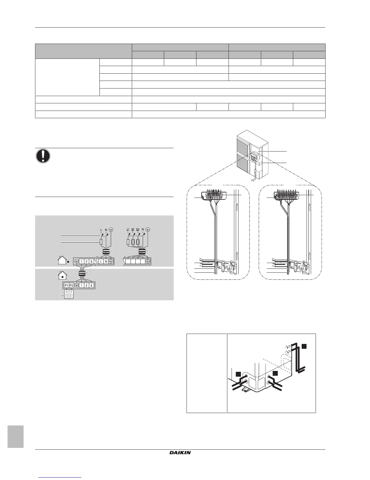
3.5.3 Toconnecttheelectricalwiringonthe
outdoorunit
NOTICE
▪ Follow the wiring diagram (delivered with the unit,
locatedattheinsideoftheservicecover).
▪ Fixtheearthwiretothestopvalveattachmentplateso
thatitdoesnotslide.
▪ Make sure the electrical wiring does NOT obstruct
properreattachmentoftheservicecover.
1 Removetheservicecover.
2 Connecttheinterconnectioncableandpowersupplyasfollows:
c
a
d
e
1~50 Hz
220-240 V
3N~50 Hz
380-415 V
V1 Y1
L1 L2 L3
L1 L2 L3
N
b
b
a Interconnectioncable
b Powersupplycable
c Earthleakagecircuitbreaker
d Fuse
e Userinterface
a Switchbox
b Stopvalveattachmentplate
c Earth
d Cabletie
e Interconnectioncable
f Powersupplycable
3 Fixthecables(powersupplyand interconnectioncable)witha
cabletietothestopvalveattachmentplate.
4 Routethewiringthroughtheframeandconnectittoit.
Routingthrough
theframe
Chooseoneofthe3possibilities:
aPowersupplycable
bInterconnectioncable