5Technicaldata
Installationmanual
10
AZQS100~140B8V1B+AZQS100~140B7Y1B
Splitsystemairconditioners
4P3855281–2014.08
4.2 Toperformatestrun
NOTICE
Donotinterruptthetestrun.
INFORMATION
In case you have to redo the test run, see the service
manual.
1 Performintroductorysteps.
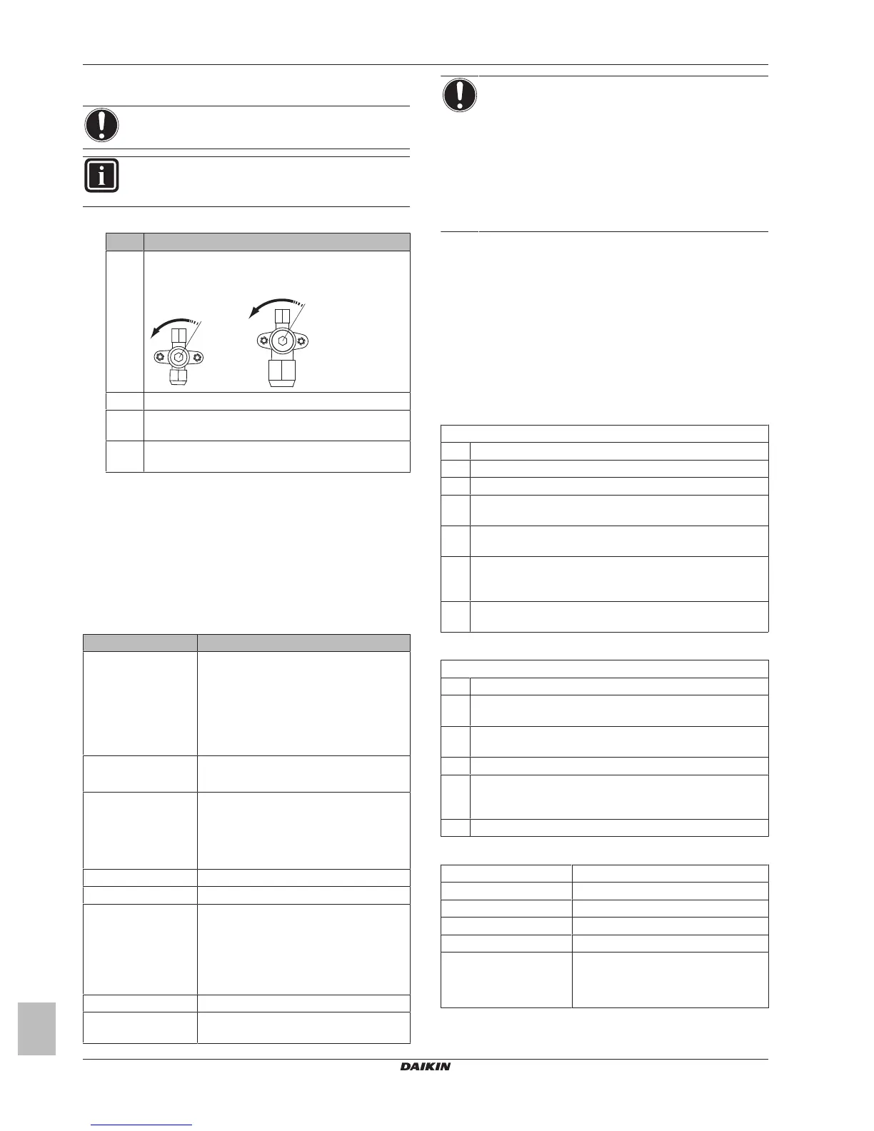
# Action
1 Opentheliquidstopvalve(A)andgasstopvalve(B)
byremovingthestemcapandturning
counterclockwisewithahexwrenchuntilitstops.
2 Closetheservicecovertopreventelectricshocks.
3 TurnONpowerforatleast6hoursbeforestarting
operationtoprotectthecompressor.
4 Ontheuserinterface,settheunittocoolingoperation
mode.
2 Ontheuserinterface,turnONtheunit.
Result: The test run starts automatically. During the test run,
the H2P test LED is ON. When the test run is done, the LED
turnsOFF.
4.3 Errorcodeswhenperforminga
testrun
Ifthe installation of theoutdoor unit has NOTbeen done correctly,
thefollowingerrorcodesmaybedisplayedontheuserinterface:
Errorcode Possiblecause
Nothingdisplayed
(thecurrentlyset
temperatureisnot
displayed)
▪ The wiring is disconnected or there is a
wiring error (between power supply and
outdoor unit, between outdoor unit and
indoor units, between indoor unit and
userinterface).
▪ The fuse on the outdoor unit PCB has
blownout.
E3,E4orL8 ▪ Thestopvalvesareclosed.
▪ Theairinletorairoutletisblocked.
E7 Thereisamissingphaseincaseofthree
phasepowersupplyunits.
Note:Operationwillbeimpossible.Turn
OFFthepower,recheckthewiring,and
switchtwoofthethreeelectricalwires.
L4 Theairinletorairoutletisblocked.
U0 Thestopvalvesareclosed.
U2 ▪ Thereisavoltageimbalance.
▪ There is a missing phase in case of
threephase power supply units. Note:
Operation will be impossible. Turn OFF
thepower,recheckthewiring,andswitch
twoofthethreeelectricalwires.
U4orUF Theinterunitbranchwiringisnotcorrect.
UA Theoutdoorandindoorunitare
incompatible.
NOTICE
▪ Thereversedphaseprotectiondetectorofthisproduct
only functions when the product starts up.
Consequently reversed phase detection is not
performedduringnormaloperationoftheproduct.
▪ Thereversed phase protection detector is designed to
stop the product in the event of an abnormality when
theproductisstartedup.
▪ Replace two of the three phases (L1, L2, and L3)
duringreversephaseprotectionabnormality.
5 Technicaldata
5.1 Wiringdiagram
5.1.1 Wiringdiagram:Outdoorunit
Thewiringdiagramisdeliveredwiththeunit,locatedattheinsideof
theservicecover.
NotesforAZQS_V1:
Notes:
1 Symbols(seelegend).
2 Colours(seelegend).
3 Thiswiringdiagramappliesonlytotheoutdoorunit.
4 Refertothewiringdiagramsticker(onthebackoftheservice
cover)forhowtousetheBS1~BS4andDS1switches.
5 Whenoperating,donotshortcircuitprotectivedevicesS1PH
andS1PL.
6 Refertotheservicemanualforinstructionsonhowtosetthe
selectorswitches(DS1).Thefactorysettingofallswitchesis
OFF.
7 Refertothecombinationtableandtheoptionmanualforhow
toconnectthewiringtoX6A,X28AandX77A.
NotesforAZQS_Y1:
Notes:
1 Thiswiringdiagramappliesonlytotheoutdoorunit.
2 Refertothecombinationtableandtheoptionmanualforhow
toconnectthewiringtoX6A,X28AandX77A.
3 Refertothewiringdiagramsticker(onthebackoftheservice
cover)forhowtousetheBS1~BS4andDS1switches.
4 Whenoperating,donotshortcircuitprotectivedeviceS1PH.
5 Refertotheservicemanualforinstructionsonhowtosetthe
selectorswitches(DS1).Thefactorysettingofallswitchesis
OFF.
6 Onlyfor71class.
Legendforwiringdiagrams:
A1P~A2P Printedcircuitboard
BS1~BS4 Pushbuttonswitch
C1~C3 Capacitor
DS1 DIPswitch
E1H Bottomplateheater(option)
F1U~F8U
(AZQS100_V1)
▪ F1U,F2U:Fuse
▪ F6U:Fuse(T3.15A/250V)
▪ F7U,F8U:Fuse(F1.0A/250V)