3Installation
Installationmanual
5
AZQS100~140B8V1B+AZQS100~140B7Y1B
Splitsystemairconditioners
4P3855281–2014.08
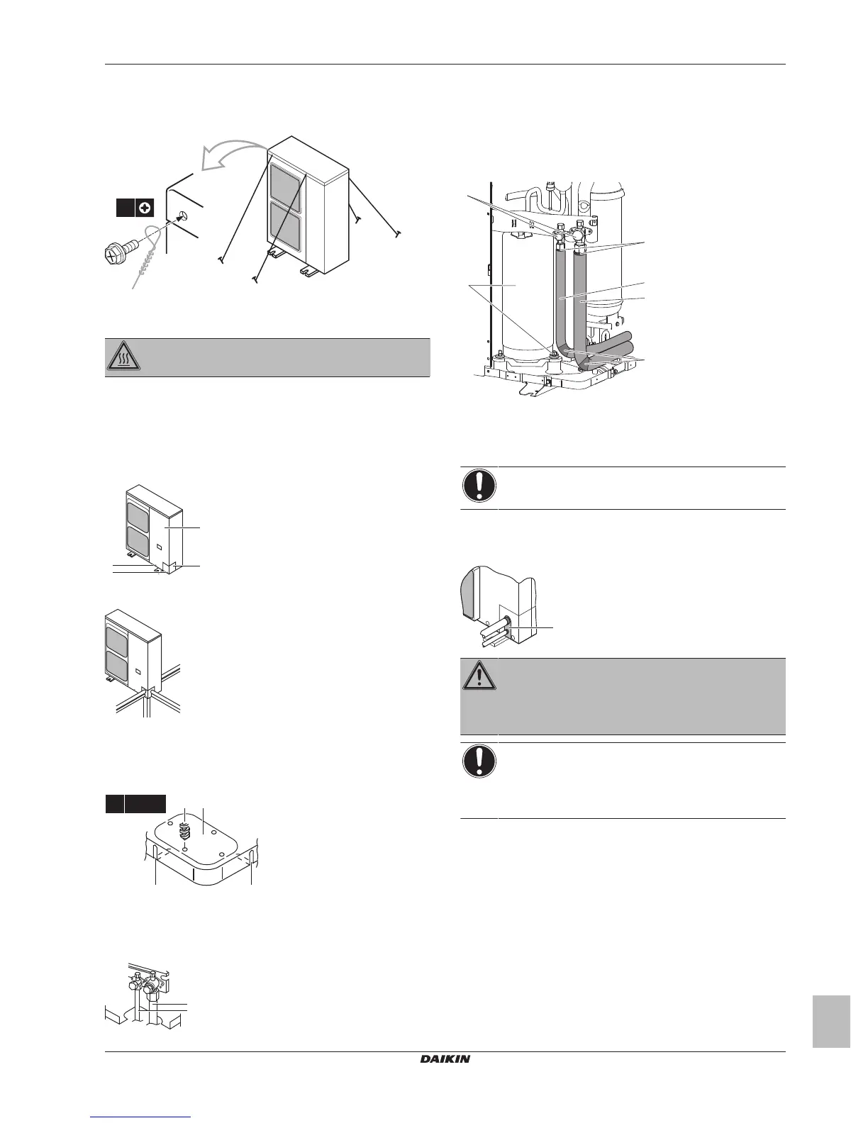
3.1.4 Topreventtheoutdoorunitfromfalling
over
Connectcables(fieldsupply)asshown:
3.2 Connectingtherefrigerantpiping
DANGER:RISKOFBURNING
3.2.1 Toconnecttherefrigerantpipingtothe
outdoorunit
1 Dothefollowing:
▪ Removetheservicecover(a)withscrew(b).
▪ Removethepipingintakeplate(c)withscrew(d).
2 Chooseapipingroute(a,b,cord).
3 Ifyouhavechosenthedownwardspipingroute:
▪ Drill(a,4×)andremovetheknockouthole(b).
▪ Cutouttheslits(c)withametalsaw.
4 Dothefollowing:
▪ Connecttheliquidpipe(a)totheliquidstopvalve.
▪ Connectthegaspipe(b)tothegasstopvalve.
5 Dothefollowing:
▪ Insulatetheliquidpiping(a)andthegaspiping(b).
▪ Wind heat insulation around the curves, and then cover it
withvinyltape(c).
▪ Make sure the field piping does not touch any compressor
components(d).
▪ Sealtheinsulationends(sealantetc.)(e).
6 If the outdoor unitis installed abovethe indoor unit,cover the
stop valves (f, see above) with sealing material to prevent
condensedwateronthestopvalvesfrommovingtotheindoor
unit.
NOTICE
Anyexposedpipingmightcausecondensation.
7 Reattachtheservicecoverandthepipingintakeplate.
8 Sealall gaps (example: a)to prevent snow andsmall animals
fromenteringthesystem.
WARNING
Provideadequatemeasurestopreventthattheunitcanbe
used as a shelter by small animals. Small animals that
makecontactwithelectricalpartscancausemalfunctions,
smokeorfire.
NOTICE
Make sure to open the stop valves after installing the
refrigerantpipingandperformingvacuum drying. Running
the system with the stop valves closed may break the
compressor.