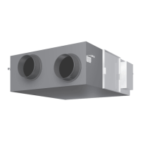
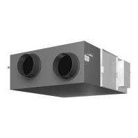
VAM350-2000FB
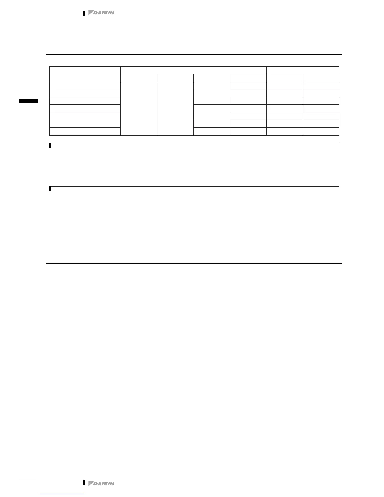
Unit model name Power supply FM
50Hz 60Hz MCA MFA kW FLA
VAM350FB
Power supply
Max.: 264V
Min.: 198V
Power supply
Max.: 242V
Min.: 198V
0.9 16 0.08 x 2 0.4 x 2
VAM500FB 1.3 16 0.08 x 2 0.6 x 2
VAM650FB 1.6 16 0.106 x 2 0.7 x 2
VAM800FB 2.5 16 0.210 x 2 1.1 x 2
VAM1000FB 3.0 16 0.210 x 2 1.3 x 2
VAM1500FB 5.0 16 0.210 x 2 2.2 x 4
VAM2000FB 5.0 16 0.210 x 2 2.2 x 4
LEGEND
MCA : minimum circuit Amps. (A)
MFA : maximum fuse Amps. (A) (see note 5)
kW : fan motor rated output (kW)
FLA : full load Amps. (A)
FM : Fan motor
NOTES
1. Voltage range:
The units are suitable for use on electrical systems where the voltage, supplied to unit terminals, is not below or above listed range limits.
2. The maximum allowable voltage variation between phases is 2%.
3. MCA = 1.25 x FLA (FM1) + FLA (FM2)
MCA represents maximum unit input current.
MFA represents acceptable capacity for MCA.
(Next lower standard fuse rating minimum 16A).
4. Select a wire size based on the MCA value.
5. Instead of a fuse, use a circuit breaker.
4D082062