3
1
15
• Ventilation • Heat reclaim ventilation
75
• Heat reclaim ventilation • VAM-FA/FB
15 Control systems
15 - 4 Applicable patterns
15 - 4 - 1 Additional functions
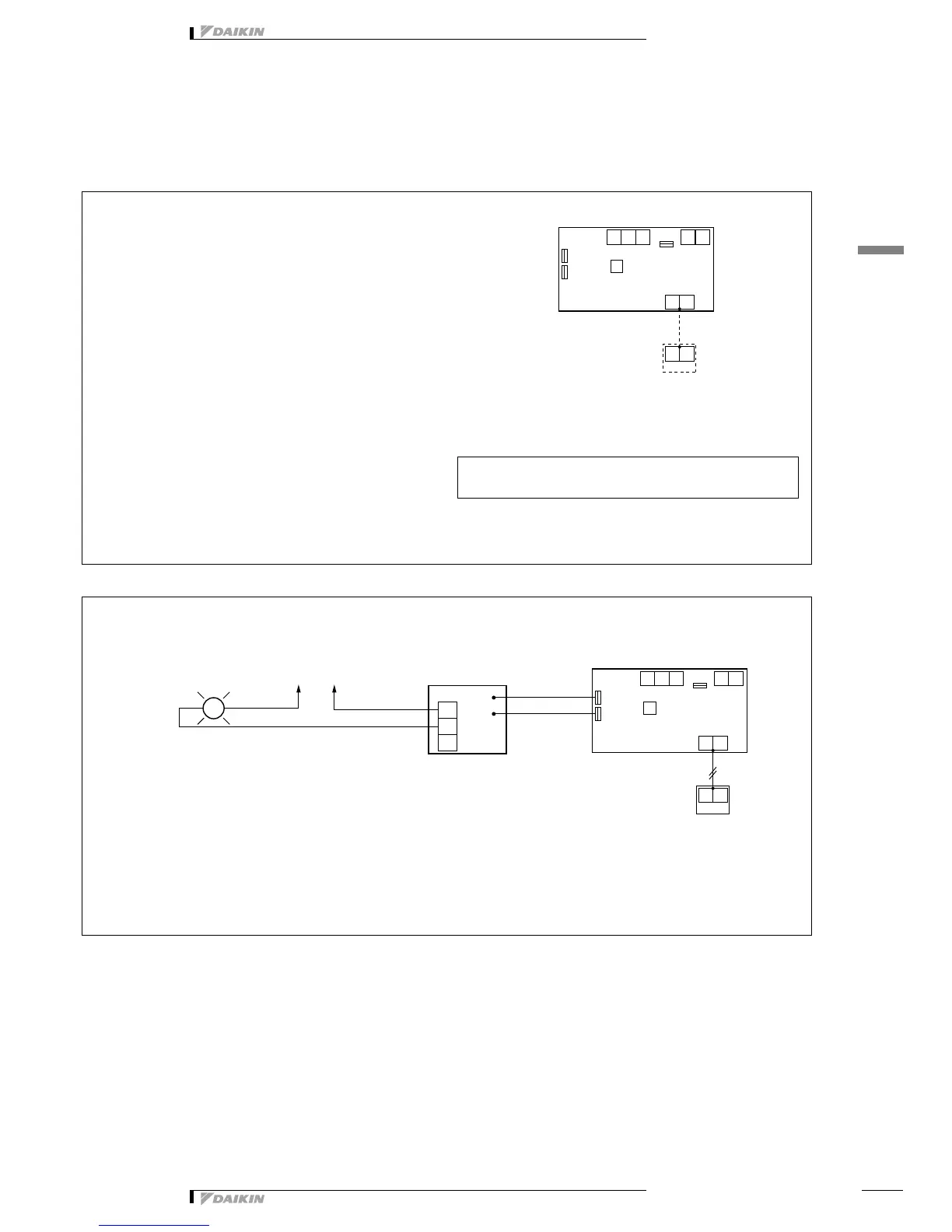
Operation by power supply [HRV unit]
Monitor of operation (KRP1C4/BRP4A50A) [HRV unit → operating pilot lamp (local supply)]
Purposes and functions
• The HRV unit is operated by “On / Off” of the main power
breaker. This is possible only for the independent operation
system. (When the main power is disconnected, the
transmission error will be displayed if the HRV unit is
interlocked to the indoor unit or controlled by the centralized
control.)
Cautions
1. Install insect control wire net on the air intake and exhaust
openings. (If the power is disconnected when the damper is
open, the damper remains open and the insects may get
into the room.)
2. When you install the remote control, it is possible to have
normal operation after the electric power is supplied.
Example of control wiring
Switch setting for HRV unit
Install the remote control for indoor unit for the initial setting. After
completion of the initial setting, remove the remote control.
Optional accessories required
• None
Purposes and functions
To monitor the operation of one HRV unit.
Example of control wiring
Switch setting for HRV unit
• No change is required. (as per factory setting)
Optional accessories required
• Adapter PCB: KRP50-2