3
1
14
• Ventilation • Heat reclaim ventilation
59
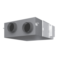
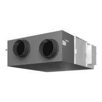
• Heat reclaim ventilation • VAM-FA/FB
14 Optional accessories
14 - 3 BRP4A50: Heater control kit
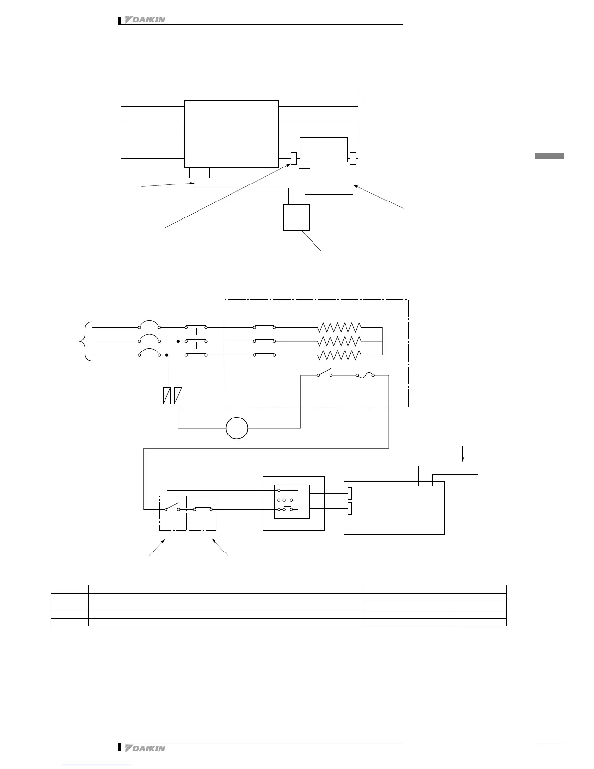
Installation example
Wiring
Note:
Make sure to install TH3 and TH4 for safety.
Test run
After completing the installation of the system, check again to make sure that no error was made in wiring or switch setting on the printed circuit
boards of the HRV units.
Then, turn on the power of the HRV units. Refer to the manual of the remote control of each unit (remote control for air conditioner, central control unit,
etc.) for conducting a trial operation.
Symbol Part Installation Place
52H Relay Install a relay box at site Field supply
EH Electric heater (Bimetal switch, Temperature fuse, Thermal cut out etc. (built in) Duct Field supply
TH3 Temperature thermostat (ON when the temperature is at or below –10°C) Duct (front of EH) Field supply
TH4 Temperature thermostat (OFF when the temperature is at or more than 5°C) Duct (behind EH) Field supply
(HC0223)
Return Air
Supply Air
Exhaust Air
Outdoor Air
HRV
Adapter
BRP4A50
Temperature thermostat (Field supply)
(Heater OFF when the temperature is at or more than 5
°C)
Temperature thermostat (Field supply)
(Heater ON when the temperature is at or below –10
°C)
Power supply (Field supply)
Relay box
Preheater
(Field supply)