3
1
9
• Ventilation • Heat reclaim ventilation
23
• Heat reclaim ventilation • VAM-FA/FB
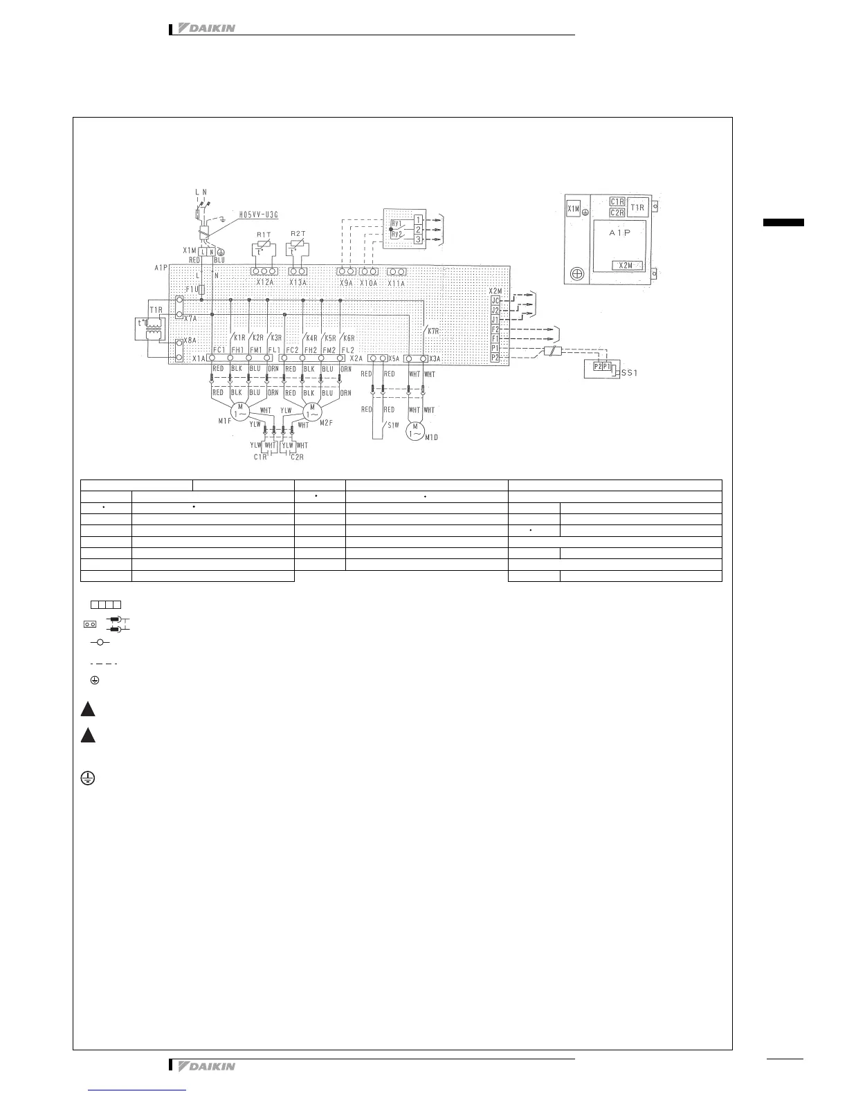
9 Wiring diagrams
9 - 1 Wiring Diagrams - Single Phase
9$0)$
2TW24836-1C
Before obtaining access to terminal devices, all power supply circuits must be interrupted.
Clean the heat exchange elements once every two years or more often and the air filter once a year or more often. (Before cleaning, make sure
that the unit is not operating.)
To prevent electric shock hazards, provide grounding work according to the installation manual.
L - RED N - BLU M2F Motor (exhaust fan motor) Optional accessories
A1P Printed circuit board Q1L Q2L Thermo switch (MF1 2 built-in) Adapter for wiring (KRP50-2)
C1R C2R Capacitor (M1F M2F) R1T Thermistor (indoor air) Ry1 Magnetic relay (On/Off)
F1U Fuse (250V, 10A) R2T Thermistor (outdoor air) Ry2 Magnetic relay (humidifier operation)
K1R ~ K3R Magnetic relay (M1F) S1W Limit switch X9A 10A Connector (KRP50-20)
K4R ~ K6R Magnetic relay (M2F) T1R Transformer (supply 220-240V/22V) Remote control
K7R Magnetic relay (M1D) X1M Terminal (power supply) SS1 Selector switch (main/sub)
M1D Motor (damper motor) X2M Terminal (control) Optional connector
M1F Motor (air supply fan motor) X11A Connector (adapter power supply)
: Terminals Colors: BLK: Black GRN: Green
: Connector BLU: Blue RED: Red
: Wire clamp BRN: Brown WHT: White
: Field wiring ORN: Orange YLW: Yellow
: Protective earth
Power supply
single phase
220-240/220V
50/60Hz
External output terminals
Terminals for the
input from outside
Terminals for the
centralized control
Remote control
(optional accessories)
Wiring diagram
Adapter for wiring
(optionl accessories) (KRP50-2)
Switch box
,
!
!