VAM350-650FB
3D080682A
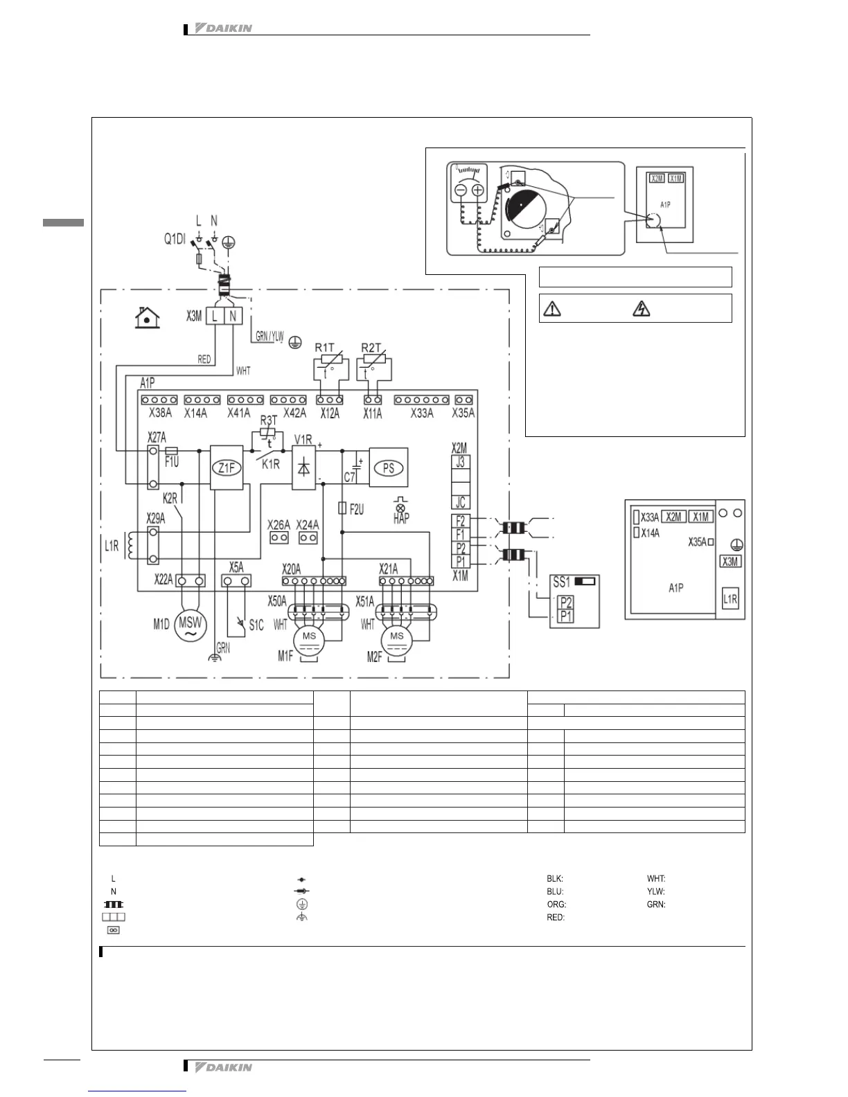
NOTES
1 In case you use the central remote control, connect it to the unit in accordance with the attached manual.
2 When connecting the input wires from outside, fresh-up or on/off control operation can be selected. (Contact with a minimum applicable load of 12V DC, 1mA)
3 For details of connection see the attached manual of the option kit.
4 SS1 (A1P) has already been set to “nor.” at factory set. The unit will not run if the setting is changed.
1 Do not open the EL. Compo. box cover for 10 minutes
after the power supply is turned off.
2 After opening the EL. Compo. box, measure the points
shown at the right with a tester and confirm that the
voltage of the capacitor in the main circuit is less than
DC50V
A1P Printed circuit board
Q1DI
Field earth leak detector
(Max. 300 mA)
REMOTE CONTROL
C1 Capacitor (M1F) SS1 Selector switch
F1U Fuse T, 6.3A, 250V (A1P) R1T Thermistor (Indoor air) CONNECTOR FOR OPTION (See note 3)
F1U Fuse T, 5A, 250V (A1P) R2T Thermistor (Outdoor air) X14A Connector (CO
2
sensor)
HAP Pilot lamp (Service monitor - green) R3T Thermistor (PTC) X24A Connector (Outside damper)
K1R Magnetic relay S1C Limit switch damper motor X26A Connector (Filter sign)
K2R Magnetic relay X1M Terminal (A1P) X33A Connector (Contact PCB)
L1R Reactor X2M Terminal (Outside input) (A1P) X35A Connector (Appendices PCB)
M1F Motor (Supply air fan) X3M Terminal (Power supply) X38A Connector (Multi tenant)
M2F Motor (Exhaust air fan) V1R Diode bridge X41A Connector (Humidity sensor 1)
M1D Motor (Damper) Z1F Noise filter X42A Connector (Humidity sensor 2)
PS Switching power supply (A1P)
: Live : Connection Colors: Black White
: Neutral : Relay connector Blue Yellow
: Field wiring : Protective earth (screw) Orange Green
: Terminal strip : Noiseless earth Red
: Connector
Printed circuit board
See note 1
Control box
Wired remote control
(opt. accessory)
Indoor
220-240V/220V
~
50/60Hz
Measuring points
for voltage
Caution when performing service
inside the EL. Compo. box
WARNING
Caution for ELECTRIC SHOCK