5 Installation
Installation manual
29
RWEQ96~432TAYCU
VRV W T-Series water-cooled system air conditioner
4P540122-1B – 2018.11
INFORMATION
The manual refrigerant charge operation will automatically
stop within 30 minutes. If charging is not completed after
30 minutes, perform the additional refrigerant charging
operation again.
11 Perform the test procedure as described in
"8 Commissioning" on page 41.
INFORMATION
After charging refrigerant:
▪ Record the additional refrigerant amount on the
refrigerant label provided with the unit and attach it to
the backside of the front panel.
▪ Perform the test procedure described in
"8 Commissioning" on page 41.
INFORMATION
Aborting the manual refrigerant charge is possible by
pushing BS3. The unit will stop and return to idle condition.
5.6.5 Final charge adjustment
It is not necessary to do this final adjustment normally, but perform
the following operation only when if the most adequate refrigerant for
the best performance is required.
Run the system for 30 minutes in cooling to allow pressures to
stabilize, then check subcooling as detailed in the following sections.
Subcooling = Condensing_temp.(TC) – (Heat exchanger liquid pipe)
Check subcooling for each outside unit by DAIKIN specified checker
and calculate the average subcooling of the outside unit using
weighted average method. (shown below)
To display the specific temperature in the unit, refer to the
instructions in the manual that comes with the kit.
Average subcooling = ((C1) x (S1) + (C2) x (S2) + (C3) x (S3) ) / (CT)
C1 = O-1 Capacity index (Outside Unit 1)
S1 = O-1 Subcooling (Outside Unit 1)
C2 = O-2 Capacity index (Outside Unit 2)
S2 = O-2 Subcooling (Outside Unit 2)
C3 = O-3 Capacity index (Outside Unit 3)
S3 = O-3 Subcooling (Outside Unit 3)
CT = Total Capacity index of Outside unit
Systems should have a subcooling of following table.
Unit: °F (°C)
Capacity
index
96 120 144 192 216 240 264
Average
subcooling
4.9
(2.7)
7.2
(4.0)
9.9
(5.5)
4.9
(2.7)
6.1
(3.4)
7.2
(4.0)
8.6
(4.8)
Capacity
index
288 312 336 360 384 408 432
Average
subcooling
9.9
(5.5)
7.6
(4.2)
6.5
(3.6)
7.2
(4.0)
8.3
(4.6)
9.2
(5.1)
9.9
(5.5)
a. If average subcooling is low, add charge to raise subcooling to
(Average subcooling)±1.8°F (1°C).
(The maximum additional charge is 4.4 lbs/unit. (2kg/unit))
b. If average subcooling is high, remove charge to lower the
subcooling to (Average subcooling)±1.8°F (1°C).
5.6.6 Checks after charging refrigerant
▪ Areallstopvalvesopen?
▪ Istheamountofrefrigerant,thathasbeenadded,recordedonthe
refrigerantchargelabel?
NOTE
Make sure to open all stop valves after (pre-) charging the
refrigerant.
Operating with the stop valves closed will damage the
compressor.
5.7 Connecting the water piping
5.7.1 About connecting the water piping
Before connecting the water piping
Make sure the outside and indoor units are mounted.
Typical workflow
Connecting the water piping typically consists of the following
stages:
1 Connecting the water piping of the outside unit.
2 Filling the water circuit.
3 Insulating the water piping.
5.7.2 Precautions when connecting the water
piping
INFORMATION
Also read the precautions and requirements in the
following chapters:
▪ Generalsafetyprecautions
▪ Preparation
5.7.3 To connect the water piping
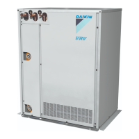
a
b
a Condenser water outlet
b Condenser water inlet
Consult "4.4.2 Water circuit requirements" on page 16 for the correct
tightening torque of the water piping connections.
5.7.4 To fill the water circuit
1 Connect the water supply hose to the fill valve (field supply).
2 Open the fill valve.
3 Run the pump ONLY and make sure that no air has been
caught in the water circulation system otherwise the plate heat
exchanger will freeze.
4 Check if the water flow rate is correct, otherwise the plate heat
exchanger will freeze. Measure any water pressure loss before
and after running the pump and make sure that the flow rate is
correct. If not, stop the pump immediately and carry out
troubleshooting.

 Loading...


