20 WGZ030D through WGZ200D OMM 1130-2
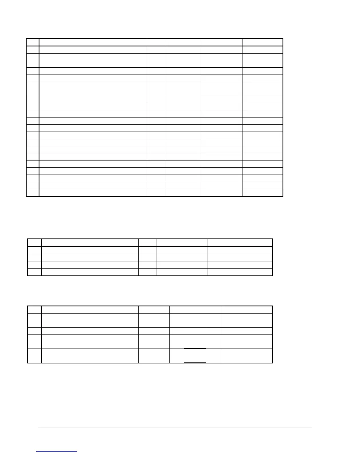
Table 6, Continued
Motor Control Relay #3 = Compr#3
*6
Condenser Fan #3– Water Cooled =N /Tower Fan
C1 /
Fan Contactor Fan OFF Fan ON
Motor Control Relay #5 = Compr#5
C1 Starter Compressor OFF Compressor ON
8
Condenser Fan #2 – Water Cooled =N /Tower Fan
#1-Water Cooled=Y
C2 /
UT
Fan Contactor Fan OFF Fan ON
Motor Control Relay #2 = Compr#2
Motor Control Relay #4 = Compr#4
Motor Control Relay #6 = Compr#6
C2 Starter Compressor OFF Compressor ON
Condenser Fan #5 C1 Fan Contactor Fan OFF Fan ON
Hot Gas Bypass #2 C2 Solenoid Cooling OFF Cooling ON
Condenser Fan #4 C2 Fan Contactor Fan OFF Fan ON
Condenser Fan #5&7
C1 Fan Contactor Fan OFF Fan ON
Expansion I/O Controller
Digital Outputs
The following parameters are digital outputs from this controller.
Types: C1 = Refrigerant Circuit #1, C2 = Refrigerant Circuit #2, UT = Unit
Evap Water Pump Output #2 UT Pump Off Pump On
Cond Water Pump Output #2
Analog Inputs
The following parameters are digital outputs from this controller for Templifier operation only.
Types: C1 = Refrigerant Circuit #1, C2 = Refrigerant Circuit #2, & UT = Unit
1
Entering Evaporator Water Temperature
UT
NTC Thermister
-58 to 212°F
3 Liquid Line Temperature #1 (R134a)
C1
NTC Thermister
(
10k@25°C)
-58 to 212°F
4 Liquid Line Temperature #2 (R134a)
C2
NTC Thermister
-58 to 212°F