EasyManua.ls Logo

DAITEM 473-29X - 10. Connecting and Testing the Connected Inputs;Outputs; 10.1 Wiring Diagram

DAITEM 473-29X
44 pages
Print Icon
To Next Page IconTo Next Page
To Previous Page IconTo Previous Page
Loading...
32
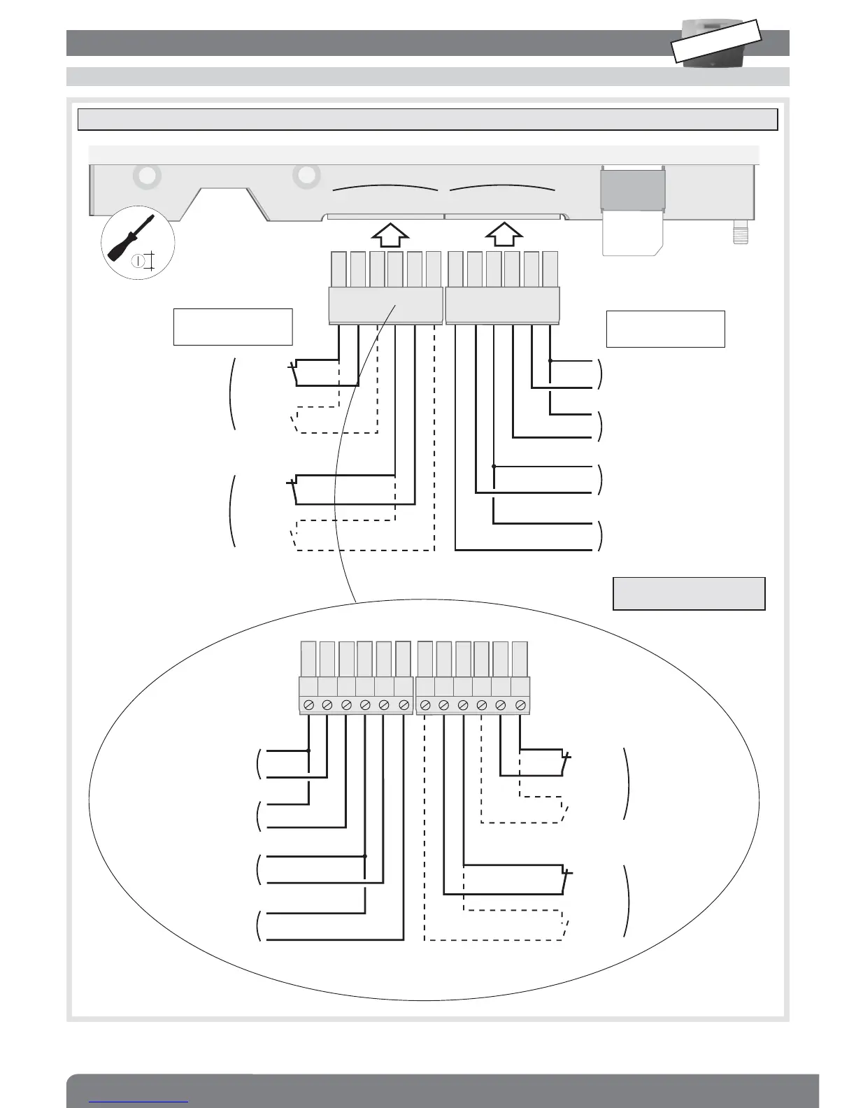
10.1 Wiring diagram
10. Connecting and testing the connected Inputs/Outputs
C1 R1 T1 C2 R2 T2 E1 E2 0V E3 E4 0V
OR
NC
output
OR
NO
output
NC
output
NO
output
O1
O2
2 outputs
4 inputs
Input 4
Input 3
Input 2
Input 1
C1 R1 T1 C2 R2 T2 E1 E2 0V E3 E4 0V
OR
NC
output
OR
NO
output
NC
output
NO
output
O1
O2
Input 4
Input 3
Input 2
Input 1
0V E4 E3 0V E2 E1 T2 R2 C2 T1 R1 C1
Screw terminal side view
Outputs: SELV 24
V/1A relay type
Inputs: SELV dry
contact type
IMPORTANT: to ensure protection against lightning all products connected to the GSM dialler must be inside the home.
Use cables with a minimum
cross-section of 0.5 mm
2
.
INSTALLATION
MODE
2.5

Table of Contents