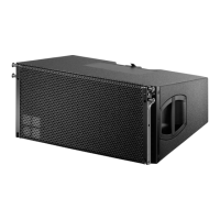
3. Z5156 Q Flying adapter
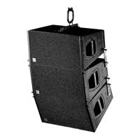
Fig. 22: 3 x Q1s with Z5156 Q Flying
adapter
The Z5156 Q Flying adapter is designed to support arrays of up to three
of the following types of loudspeakers:
Code Type Weight incl. array links
Z0501 Q1 23 kg (51 lb)
Z0507 Q7 23 kg (51 lb)
Z0511 Q10 23 kg (51 lb)
The weight of the Q Flying adapter is 0.8 kg (1.76 lb)
3.1. Load capacity/System safety
WARNING!
The Z5156 Q Flying adapter is designed to suspend up to
three d&b Q1, Q7 or Q10 loudspeaker cabinets. The
Working Load Limit (WLL) for the adapter is 72 kg (159
lb).
Make sure that the Working Load Limit (WLL) of the
suspension point is high enough to carry the total system
weight.
3.2. Suspension of the Q Flying adapter
Fig. 23: Q Flying adapter hole grid
Fig. 24: Q Flying adapter and Z5147 Rota
clamp
[S]
[1]
Fig. 25: Q Flying adapter [1] and securing
pin [S]
1.
2.
3.
4.
G
S
Fig. 26: Q cabinet quick lock mechanism
The Q Flying adapter is equipped with nine locating holes 12.5 mm
(0.5“) at 30 mm (1.2”) spacings. With arrays up to three cabinets
ArrayCalc displays the Q Flying adapter hole position to achieve the
desired vertical aiming.
The Q Flying adapter can be suspended using an E6502 1t Shackle and
steel wire ropes or the Z5147 Rota clamp. Choose the appropriate hole
position in the Q Flying adapter according to the ArrayCalc simulation.
3.3. Assembly
The Z5156 Q Flying adapter is connected to the quick lock adapter plate
of the first cabinet as follows (Fig. ):
Attach the Q Flying adapter's fixing plate into the recessed holes in the
cabinets quick lock adapter plate.
Slide the adapter towards the back of the cabinet until it is fixed in
place.
Insert the securing pin [S] into the aligned socket.
Ensure that the securing pin [S] is locked. A groove [G] in the
bolt of the securing pin indicates that it is properly locked.
Connect up to two more cabinets using Z5151 Q Front links, Z5152 Q
Splay links and Z5153 Q Locking pins 8 mm as described in section
2.3 Assembly of the array on page 7.
For safety reasons the final array must be fitted with an additional
safety device which is independent of the suspension points. A detailed
description is given in section 4. Secondary safety on page 12.
Q-Series Rigging manual (1.2EN) Page 11 of 20
 Loading...