END USER MANUAL
OPERATION AND MAINTENANCE OF HIGH PRESSURE WATER MIST PUMP UNIT
REVISION 4, MAY 2016
Lamp which indicates that the SEM-SAFE
®
High-Pressure Water Mist
Pump Unit is connected to supply. Lamp should be turned on at all
times during operation.
Emergency supply
switchboard
Lamp which indicates that the SEM-SAFE
®
High-Pressure Water Mist
Pump Unit is connected to the emergency supply. Lamp should be
turned on at all times during operation.
Button for manual start of the SEM-SAFE
®
High-Pressure Water Mist
Pump Unit. By pressing the button, the first pump on the unit will start.
Then the SEM-SAFE
®
High-Pressure Water Mist Pump Unit will
automatically control the pressure level and turn on additional high-
pressure pumps if required.
Lamps which turn on when a specific high-pressure pump on the SEM-
SAFE
®
High-Pressure Water Mist Pump Unit is running. There is a
separate lamp for each high-pressure pump.
Lamp which turns on when the standby high-pressure pump on the
SEM-SAFE
®
High-Pressure Water Mist Pump Unit is running.
Used for locking main door of UCP.
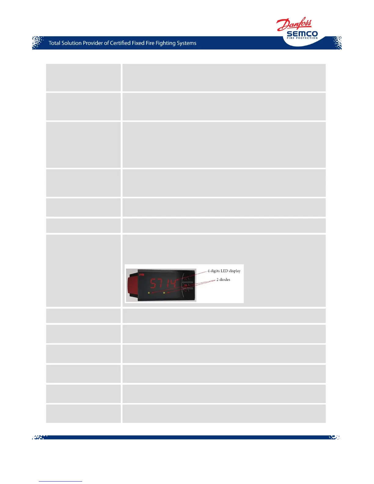
System pressure display shows the pressure level in the system and
controls the work of the pilot pump. It consists of 4 digits display and 2
relay indicators in a 14-segment LED display.
Switch for manual start of emergency supply.
Fault from foam unit
(optional)
Indicates the failure in the SEM-SAFE
®
High-Pressure Water Mist
Pump Unit from the foam unit.
Button for manual stop of the SEM-SAFE
®
High-Pressure Water Mist
Pump Unit.
Buttons for manual opening of section valves in the system. Each valve
has its own button.
Switches for manual closing of section valves in the system. Each valve
has its own button.
Display showing which actuator valves are open. Each valve is
represented by one light.