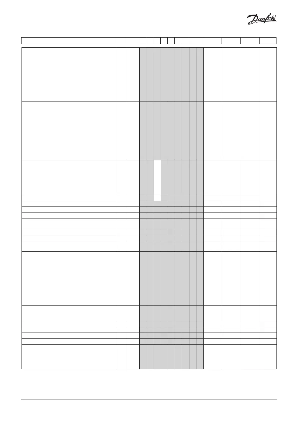
Single Coil - continued R-W Code 1 2 3 4 5 6 7 8 9 Min. Max. Fac. Actual
Refrigerant setting:
1=User defined. 3-digits. 2=R22. 3=R134a. 4=R502.
5=R717. 6=R13. 7=R13b1. 8=R23. 9=R500. 10=R503.
11=R114. 12=R142b. 13=User defined. 14=R32.
15=R227. 16=R401A. 17=R507. 18=R402A. 19=R404A.
20=R407C. 21=R407A. 22=R407B. 23=R410A. 24=R170.
25=R290. 26=R600. 27=R600a. 28=R744. 29=R1270.
30=R417A. 31=R422A. 32=R413A. 33=R422D.
34=R427A. 35=R438A. 36=R513A. 37=R407F.
38=R1234ze. 39=R1234yf. 40=R448A. 41=R449A.
42=R452A
1-3* o30 1 1 1 1 1 1 1 1 1 0 42 0
Input signal on DI2. Function:
(0=not used. 1=status on DI2. 2=door function with
alarm when open. 3=door alarm when open. 4=defrost
start (pulse-signal). 5=ext. main switch 6=night
operation 7=thermostat band changeover (activate
r21). 8=alarm function when closed. 9=alarm function
when open. 10=Appliance cleaning (pulse signal).
11=forced cooling at hot gas defrost). 12=Open night
cover, 13=coordinated defrost).14=Refrigeration
stopped (forced closing). 15=case shutdown. 16=light.
20=Refrigerant alarm. 21= adaptive liquid control
when short-circuited.
1-2* o37 1 1 1 1 1 1 1 1 1 0 21 0
Configuration of light function: 1=Light follows
day /night operation, 2=Light control via data
communication via ‘o39’, 3=The light is controlled
with a door switch on a DI input, 4=As "2", but light
switches on and night cover will open if the network
cuts out for more than 15 minutes. 5=Light controlled
via a DI input.
1-2 o38 1 1 1 1 1 1 1 1 1 5 1
Activation of light relay (only if o38=2) On=light 1-2 o39 1 1 1 1 1 1 1 1 0/Off 1/On 0/Off
Rail heat On time during day operations
1-2 o41 1 1 1 1 1 1 1 1 1 0 % 100 % 100
Rail heat On time during night operations
1-2 o42 1 1 1 1 1 1 1 1 1 0 % 100 % 100
Rail heat cycle time (On time + Off time) 1-2 o43 1 1 1 1 1 1 1 1 1 1 min. 60 min. 5
Appliance cleaning. 0=no Appliance cleaning. 1=Fans
only. 2=All output Off.
1-2 o46 1 1 1 1 1 1 1 1 1 0 2 0
Selection of wiring diagram. See overview pages 2-4 1-3* o61 1 1 1 1 1 1 1 1 1 1 9 1
Access code 2 (partial access) 2-2 o64 1 1 1 1 1 1 1 1 1 0 999 0
Replace the controller's factory settings with the
present settings
3-3* o67 1 1 1 1 1 1 1 1 1 0/Off 1/On 0/Off
Input signal on DI3. Function: (high voltage input)
(0=not used. 1=status on DI2. 2=door function with
alarm when open. 3=door alarm when open. 4=defrost
start (pulse-signal). 5=ext. main switch 6=night
operation. 7=thermostat band changeover (activate
r21). 8=Not used. 9=Not used. 10=Appliance cleaning
(pulse signal). 11=forced cooling at hot gas defrost.
12=Open night cover. 13=Not used. 14=Refrigeration
stopped (forced closing)). 15=case shutdown.
16=light. 20=Refrigerant alarm. 21= adaptive liquid
control when short-circuited.
1-2* o84 1 1 1 1 1 1 1 1 1 0 21 0
Rail heat control
0=not used, 1=pulse control with timer function (o41
and o42), 2=pulse control with dew point functionA
1-2 o85 1 1 1 1 1 1 1 1 1 0 2 0
Dew point value where the rail heat is minimum
1-2 o86 1 1 1 1 1 1 1 1 1 -10°C "o87" 8
Dew point value where the rail heat is 100% on
1-2 o87 1 1 1 1 1 1 1 1 1 "o86" 50 °C 17
Lowest permitted rail heat effect in %
1-2 o88 1 1 1 1 1 1 1 1 1 0 % 100 % 30
Time delay from "open door” refrigeration is started
1-2 o89 1 1 1 1 1 1 1 1 1 0 min. 240 min. 30
Fan operation at stopped cooling (forced closing):
0= Stopped (defrost allowed)
1= Running (defrost allowed)
2= Stopped (defrost not allowed)
3= Running (defrost not allowed)
1-2 o90 1 1 1 1 1 1 1 1 1 0 3 1
© Danfoss | DCS (vt) | 2019.07
AN294432763974en-000201 | 13

 Loading...


