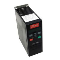
AKD 2800
Programming
Torque [%] denotes the motor’s present load in
relation to the motor’s rated torque.
Power [kW] gives the present power that the
motor is absorbing in kW.
Power [HP] gives the present power that the
motor is absorbing in HP.
Motor voltage[V] gives the voltage supplied to the motor.
DC link voltage [V] gives the intermediate circuit
voltage of the frequency converter.
Thermal load motor [%] gives the calculated/estimated
load on the motor. 100 % is the cut-out limit.
Thermal load [%] gives the calculated/estimated
thermal load on the frequency converter. 100
% is the cut-out limit.
Running hours [Hours] gives the number of hours that
the motor has tun since the last reset in parameter
619 Reset of running hours counter.
Digital input [Binary code] gives the signal status
from the 5 digital inputs (18, 19, 27, 29 and 33).
Terminal 18 corresponds to the bit on the extreme
left. ‘0’ = no signal, ‘1’ = signal connected.
Analog input 53 [V] gives the voltage value of terminal 53.
Analog input 60 [mA] gives the present value
of terminal 60.
Pulse reference [Hz] givesthereferenceinHz
connected to terminal 33.
External reference [%] gives the sum of
external references as a percentage (sum of
analogue/pulse/serial communication) in the
range from Minimum reference, Ref
MIN
to
Maximum reference, Ref
MAX
.
Status word [Hex] gives one or several status
conditions in a Hex code. See Serial communication
in the Design Guide for further information.
Heatsink temp.[°C] gives the present heatsink
temperature of the frequency converter. The
cut-out limit is 90-100°C, while cutting back
in occurs at 70 ± 5°C.
Alarm word [Hex] gives one or several alarms
in hex code. See Serial communication in the
Design Guide for further information.
Control word [Hex] gives the control word for the
frequency converter. See Serial communication in
the Design Guide for further information.
Warning word [Hex] gives one or several warnings
in hex code. See Serial communication in the
Design Guide for further information.
Extended status word [Hex] gives one or several status
modes in Hex code. See Serial communication in
the Design Guide for further information.
Communication option card warning [Hex] gives a
warning word if there is a fault in the communication
bus. Only active if communication options are installed.
If there are no communication options 0
Hex is displayed.
Pulse count gives the number of pulses that
the unit has registered.
010 Small display line 1.1
(DISPLAY LINE 1.1)
Value:
See par. 009 Large display readout
✭ Reference [%] [1]
Function:
In this parameter, the first of three data values
can be selected that is to be displayed in the LCP
controlunitdisplay,line1,position1. Thisisauseful
function, e.g. when setting the PID regulator, as
it gives a view of process reactions to reference
changes. The display readout is activated by
pushing the [DISPLAY STATUS] key.
Description of choice:
See parameter 009 Large display readout.
011 Small display readout 1.2
(DISPLAY LINE 1.2)
Value:
See parameter 009 Large display readout
✭ Motor current [A][6]
Function:
See the functional description given under parameter
010 Small display readout.
✭
= factory setting. () = display text [] = value for use in communication via serial communication port
MG.28.H2.02 -
15
 Loading...


