Pin
No.
Schematic
acronym
Function Description Reading using a
digital voltmeter
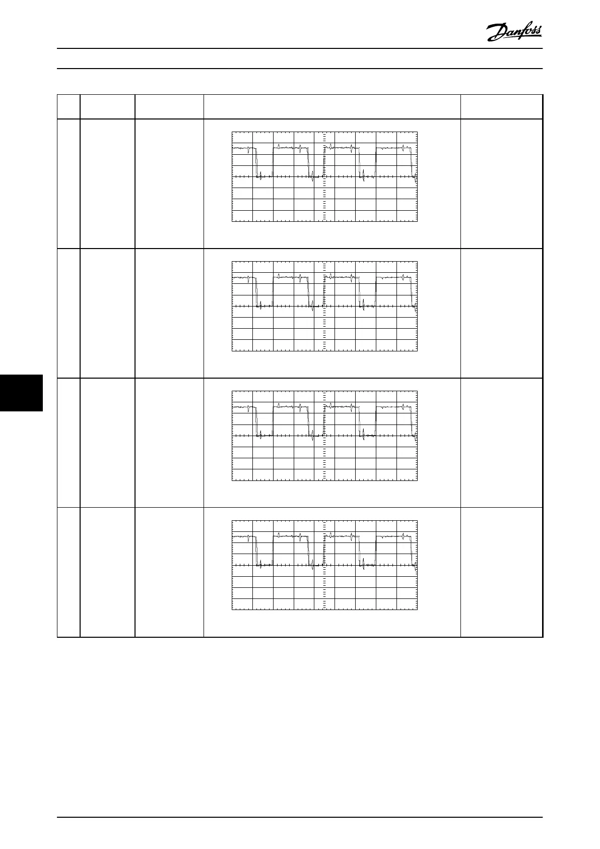
27 GVP_T IGBT gate signal,
buered, V phase,
positive. Signal
originates on
control card.
8.00
6.00
4.00
2.00
0.00 V
-2.00
-4.00
-6.00
-8.00
-4.0ms 50Us/Div
Input A
130BX153.10
2v/div 100us/div Run at 10 Hz
2.2–2.5 V DC
Equal on all phases
TP25–TP30
28 GVN_T IGBT gate signal,
buered, V phase,
negative. Signal
originates on
control card.
8.00
6.00
4.00
2.00
0.00 V
-2.00
-4.00
-6.00
-8.00
-4.0ms 50Us/Div
Input A
130BX153.10
2v/div 100us/div Run at 10 Hz
2.2–2.5 V DC
Equal on all phases
TP25–TP30
29 GWP_T IGBT gate signal,
buered, W
phase, positive.
Signal originates
on control card.
8.00
6.00
4.00
2.00
0.00 V
-2.00
-4.00
-6.00
-8.00
-4.0ms 50Us/Div
Input A
130BX153.10
2v/div 100us/div Run at 10 Hz
2.2–2.5 V DC
Equal on all phases
TP25–TP30
30 GWN_T IGBT gate signal,
buered, W
phase, negative.
Signal originates
on control card.
8.00
6.00
4.00
2.00
0.00 V
-2.00
-4.00
-6.00
-8.00
-4.0ms 50Us/Div
Input A
130BX153.10
2v/div 100us/div Run at 10 Hz
2.2–2.5 V DC
Equal on all phases
TP25–TP30
Table 9.2 Signal Test Board Pins
Special Test Equipment
VLT
®
FC Series, D1h–D8h, Da2/Db2/Da4/Db4, E1h–E4h, J8/J9
128 Danfoss A/S © 02/2019 All rights reserved. MG94A502
99
 Loading...


