10.3 D5h/D6h Disassembly and Assembly
The D5h and D6h drives are D1h drives with extended
options cabinets. The drive proled here includes a
contactor, disconnect, and brake option, and is 690 V
power range. Some procedures apply to all congurations,
but some vary depending on the size of the enclosure,
extended options cabinet, and selected options.
10.3.1 Accessing the Heat Sink Fan in
D5h/D6h Drives
D5h and D6h drives include an extended options cabinet
mounted below the heat sink fan. To access the heat sink
fan in D5h/D6h drives, remove the busbars between the
main enclosure and the extended options cabinet using
the following steps. In drives with dierent option congu-
rations, the busbars can vary slightly from the illustrations.
Disassembly
1. Remove the air bae covering the interior
components.
2. Remove the EMC shield by removing 2 screws
(T25).
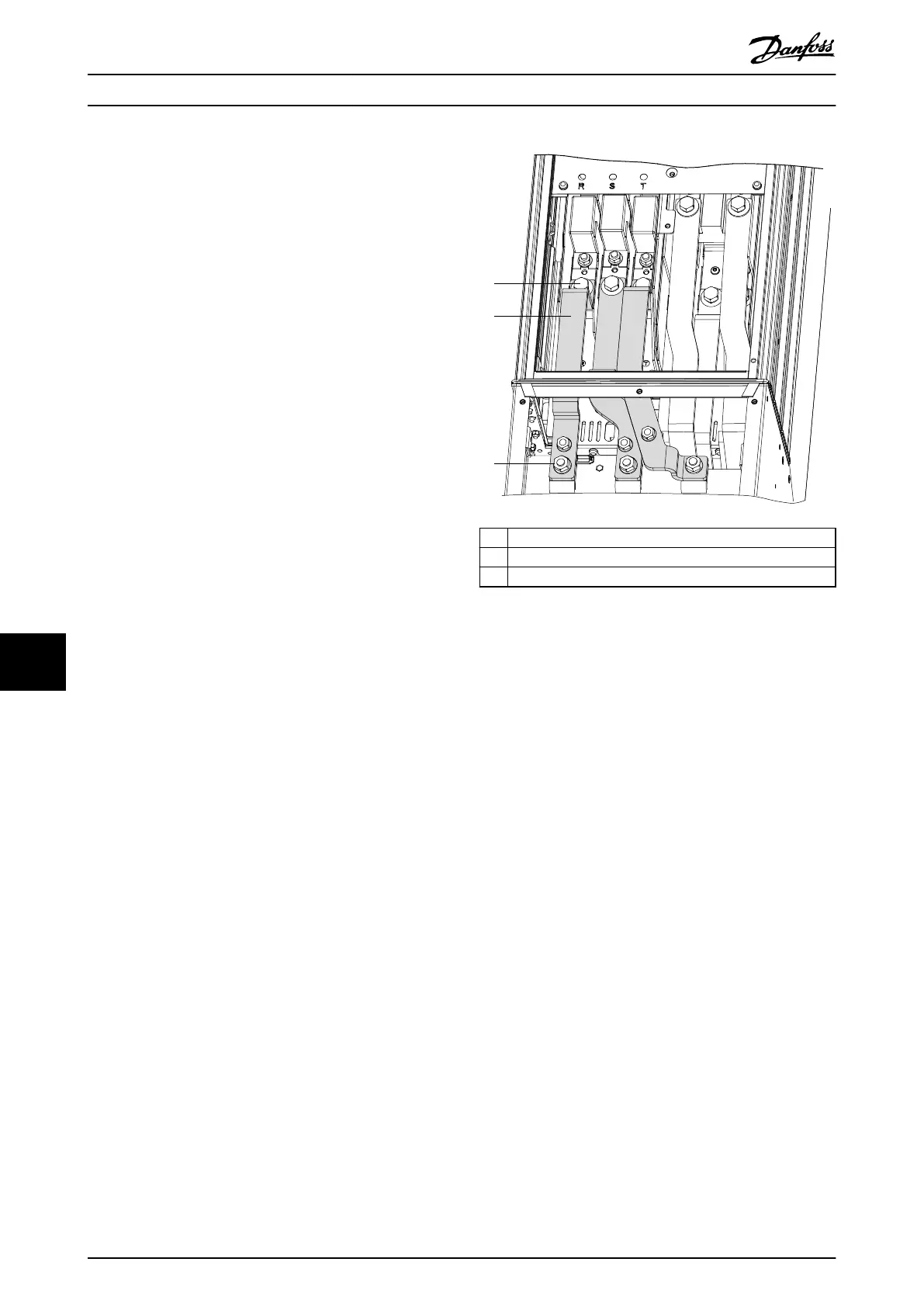
3. Remove the 3 mains input jumper busbars (R, S,
and T) between the main enclosure and the
extended options cabinet. See Illustration 10.29:
3a Remove 3 screws (17 mm) from the top
of the mains input jumper busbars, 1
per busbar.
3b Remove 3 nuts (13 mm) from the
bottom of the mains input jumper
busbars, 1 per busbar.
1 Screw (17 mm)
2 Mains input jumper busbars
3 Nut (13 mm)
Illustration 10.29 Mains Input Jumper Busbars in D5h/D6h
D1h/D3h/D5h/D6h/J8 Drive Di...
VLT
®
FC Series, D1h–D8h, Da2/Db2/Da4/Db4, E1h–E4h, J8/J9
178 Danfoss A/S © 02/2019 All rights reserved. MG94A502
1010
 Loading...


