FC 300 Design Guide
Introduction to FC 300
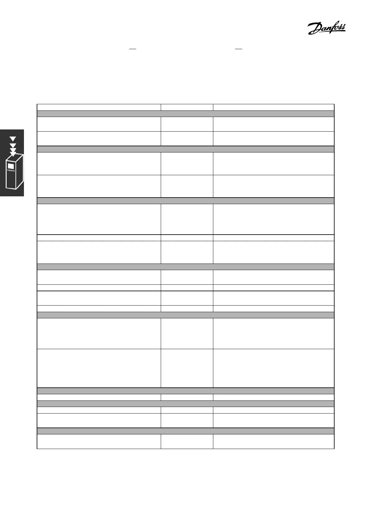
1. Start/Stop via switch connected to terminal 18.
2. Temperature reference via potentiometer ( 23 - 95°F (-5 - 35°C), 0-10 VDC) connected to te rm inal 53.
3. Temperature feed back via transmitter (14 -104°F (-10-40°C), 4-20 mA) connected to
terminal 54. Switch S202 set to ON (current input).
Function Par. no. Setting
1) Make sure the motor runs prop erly. Do the following:
Set the motor parameters using n am eplate
data
1-2* As specified by motor name plate
Have the adjustable frequency drive make an
Automatic Motor Adaptation
1-29 [1] Enable complete AMA
2) Check that the motor is running in the right direction.
Press the "Hand On" LCP key. Check that the
motor is running and note in which direction
it is turning.
Set a positive reference.
If the motor was turning in the wrong direction,
remove the motor plug and switch two of the
motor phases.
3) M ake sure the adjustable frequency drive limits are set to safe values
Check that the ramp settings are within
capabilities of the adjustable frequency
drive and allowed application operating
specifications.
3-41
3-42
3sec. (default)
3sec. (default)
Prohibit the motor from reversing if necessary 4-10 [0] Clockwise
Set acceptable limits for the motor speed and
frequency
4-11
4-13
4-19
300 RPM
1500 RPM (default)
60 Hz (default 132 Hz)
4) Configure the reference to the Proces s Control
Allow for an "asymm etrical" reference range by
selecting the "Min - Max" Reference Range
3-00 [0]Min-Max
Selecttheappropriatereferenceunit 3-01 [13] °C
Set acceptable limits for the sum of all
references
3-02
3-03
-5 °C
35 °C
Set up Analog Input 53 as a reference resource 3-15 Not necessary (default)
5) Scale the analog inputs used for reference and feedback
Scale the Analog Input 1 (terminal 53) that
is used for the te mperature reference via
potentiometer (23 - 95°F/ -5 - 35°C, 0-10
VDC).
6-10
6-11
6-14
6-15
0VDC
10 VDC
-5 °C
35 °C
Scale the Analog Input 2 (terminal 54) that
is used for the tem perature fe edback via
transmitter (14-104°F/ -10 - 40°C, 4-20 mA)
6-22
6-23
6-24
6-25
6-26
4mA
20 mA
-10 °C
40 °C
0.001 s. (default)
6) Configure the feedback to the Proce ss Control
Set up Analog Input 54 as a feedback resource 7-20 [2] Analog input 54
7) Tune the P roce ss Control PI D parameters
Select inverse control. 7-30 [1] Inverse
Use the tuning guidelines when relevant or
tune manually
7-3* See the guidelines below
8) Finished!
Save the p arameter setting s to the LCP for
safekeeping
0-50 [1] All to LCP
40
MG.33.B3.22 - VLT is a registered Danfoss trademark
 Loading...


