FC 300 Design Guide
How to Install
" Electrical Installation, Control Cables
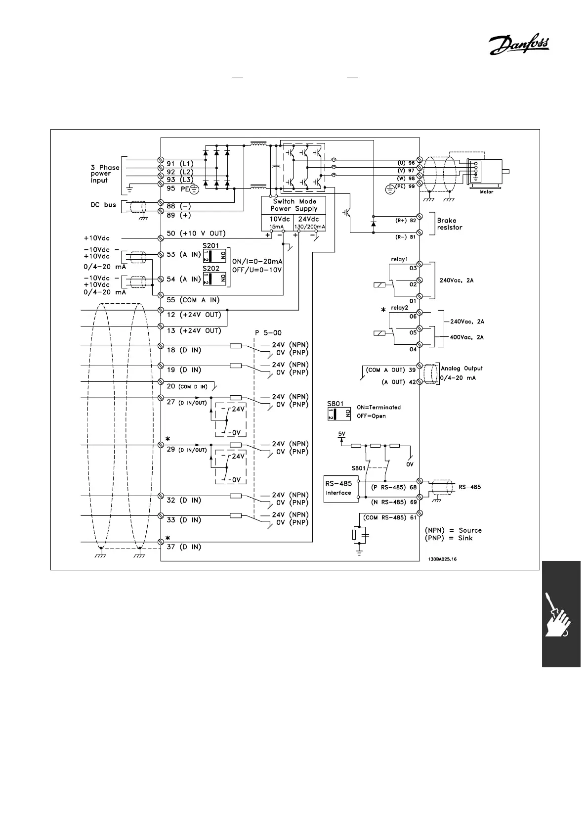
Diagram showing
all electrical terminals. Terminal 37 is not included in F C 301.
Very long con
trol cables a nd analog signals may in rare cases, depending on installation, result
in 50/60 Hz ground loops due to noise from mains supply ca bles.
If this occurs, you may have to break the shield or insert a 100 nF capacitor between shield and chassis.
The digital and analog inputs and outputs must be connected separately to the FC 300 common
inputs (terminal 20, 55, 39) to avoid ground currents from both groups affecting other groups. For
example
, switching on the digital input may disturb the analog input signal.
95
MG.33.B3.22 - VLT is a registered Danfoss trademark
 Loading...


