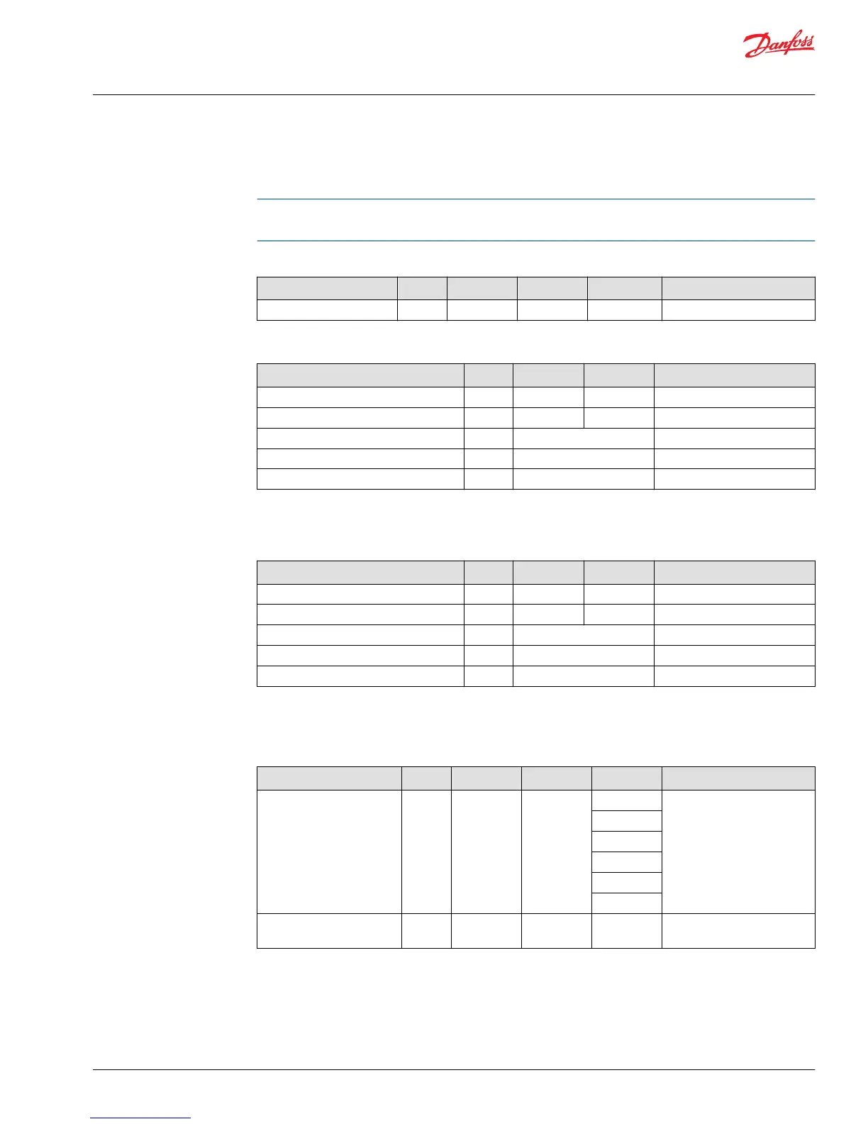
CAN shield/analog inputs
The CAN shield pin on the unit can be used as a non-configurable analog input.
The values in the following table assumes that software compensates for errors in the analog to digital
(A/D) converter.
CAN shield
Description Unit Minimum Maximum Typical Comment
Input impedance — — — 0.68 μF + 1 Ω —
Analog input (5 V only)
Description Unit Minimum Maximum Comment
Allowed voltage at pin V 0 36 —
Measuring range V 0 5.75 —
Resolution mV 1.4 —
Worst case error mV ±(20 + U*2%) —
Input impedance kΩ 233 ± 3 —
Analog input
Analog input (5 V only)
Description Unit Minimum Maximum Comment
Allowed voltage at pin V 0 36 —
Measuring range V 0 5.75 —
Resolution mV 1.4 —
Worst case error mV ±(20 + U*2%) —
Input impedance kΩ 233 ± 3 —
CAN communication
CAN communication
Description Unit Minimum Maximum Typical Comment
Available baud rates kBd 50 1000 50 With 120 Ω termination.
The default baud rate is
250kbit.
100
125
250
500
1000
Maximum input voltage
range
V 0 36 — —
Gateway channels
PLUS+1
®
Service Tool can be connected to the CAN bus by using the following gateway channels.
Technical Information
DP7XX Series Displays
Controller Area Network (CAN) specifications
©
Danfoss | November 2016 L1315553 | BC00000223en-US0504 | 15
 Loading...