D—Input/output options
Code Description
01 User configurable
1 CAN, 2 AIN/DIN, 2 DIN/AIN/FreqIn/Rheo/4-20 mA IN, DOUT
2 CAN, 2 DIN/AIN/FreqIn/Rheo/4-20 mA IN, DOUT
02 User configurable
1 CAN, 2 AIN/DIN, 2 DIN/AIN/FreqIn/Rheo/4-20 mA IN, 2 Video IN, DOUT
2 CAN, 2 DIN/AIN/FreqIn/Rheo/4-20 mA IN, 2 Video IN, DOUT
E—Flash memory/application key
Code Description
02 512 MB/without application key
F—USB port type
Code Description
04 USB device rear/USB host rear or front
02 USB device rear/USB host rear
G—Application log (vault memory)
Code Description
01 16 MB
H—Bezel color
Code Description
00 Black
01 Gray
Related products
Connector bag assemblies
Description Part numbers
12-pin connector kit (16 to 20 AWG) 10102025
12-pin connector kit (20 to 24 AWG) 10100944
Mating connector kit with camera cable
*
11130520
USB cable (device only) 11130518
USB cable (device and host) 11130519
*
Only valid for DP710, DP720, and DP730.
Connection tools
Description Part numbers
Crimp tool 16 to 20 AWG 10100744
Crimp tool 20 to 24 AWG 10100745
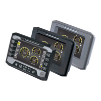
Technical Information
DP7XX Series Displays
Ordering information
©
Danfoss | November 2016 L1315553 | BC00000223en-US0504 | 9
 Loading...