VI.KT.G2.02 © Danfoss 05/2007 DH-SMT/DK
DH-SMT/DK VI.KT.G2.02 © Danfoss 05/2007
Table of Contents
Introduction ..................................................................................................6
Settings overview 7
Daily use ........................................................................................................8
Temperatures 8
Select control mode 9
Set your personal schedule 9
Maintenance ............................................................................................... 11
Date - time 1000 11
Flow temp. (flow temperature control) 2000 11
Slope 2175 12
Displace (parallel displacement) 2176 14
Temp. min. (flow temp. limit, min.) 2177 14
Temp. max. (flow temp. limit, max.) 2178 14
Room T limit (room temperature limitation) 3000 15
Intgr. time (time constant for room temp.) 3015 17
Gain - max. (room temp. limitation, max.) 3182 17
Gain - min. (room temp. limitation, min.) 3183 17
Return T limit (return temp. limitation) 4000 18
Limit (return temp. limitation) 4030 18
Gain - max. (return temp. limitation - max. influence) 4035 19
Gain - min. (return temp. limitation - min. influence) 4036 19
Intgr. time (time constant for return temp. limitation) 4037 20
Priority (priority for return temp. limitation) 4085 20
Optimize 5000 21
Auto-reduct (setback temp. dependent on outdoor temp.) 5011 21
Boost 5012 21
Ramp (reference ramping) 5013 22
Optimizer (optimizing time constant) 5014 22
Based on (optimization based on room / outdoor temp.) 5020 23
Total stop 5021 24
S1 T filter (outdoor temp. filter) 5081 24
Cut-out (limit for heating cut-out) 5179 25
Control param. (control parameters) 6000 26
Motor prot. (motor protection) 6174 26
Xp (proportional band) 6184 26
Tn (integration time constant) 6185 26
M1 run (running time of the motorized control valve) 6186 26
Nz (neutral zone) 6187 27
Line Page
Safety Note
To avoid injury of persons and damages to the device, it is absolutely necessary to read and
observe these instructions carefully. The warning sign is used to emphasize special conditions
that should be taken into consideration.
This symbol indicates that this particular piece of information should be read with
special attention.
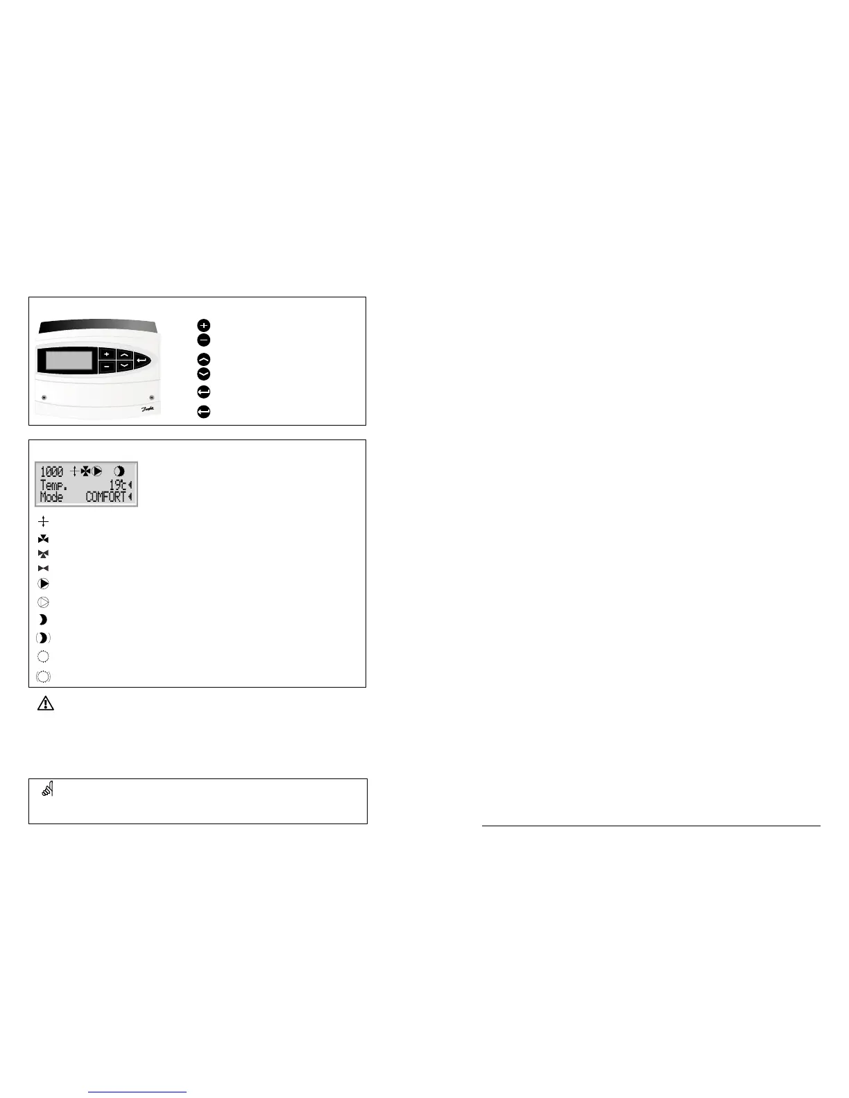
How to navigate?
Adjust temperatures and values.
Switch between menu lines.
Select / return.
2 sec.
Return to daily user menu.
What do the symbols mean?
The desired flow temperature is influenced by for example room or return temperature.
The actuator closes the control valve.
The actuator opens the control valve.
The actuator does not activate the valve.
The pump is ON.
The pump is OFF.
The controller is in setback mode.
The controller is in pre-setback mode (the symbol is blinking).
The controller is in comfort mode.
The controller is in pre-comfort mode (the symbol is blinking).
 Loading...