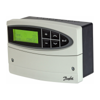
* Optional connections for safety thermostat
Terminal Description Max.
load
20 Supply voltage 24 V a.c. - A1
21 Supply voltage 24 V a.c. - A2
22 Optional connections for safety thermostat
23 Optional connections for safety thermostat
24 M1 Actuator - open, alt. thermo actuator (ABV) 15 VA
25 M1 Actuator - close 15 VA
26 M1 Actuator - A1
27 Not to be used
28 Not to be used
29 P1 Phase for circulation pump (relay R2)
30 P1 Relay R2 4 (2) A
Wire cross section: 0.5 - 1.5 mm
2
Incorrect connection can damage the TRIAC outputs.
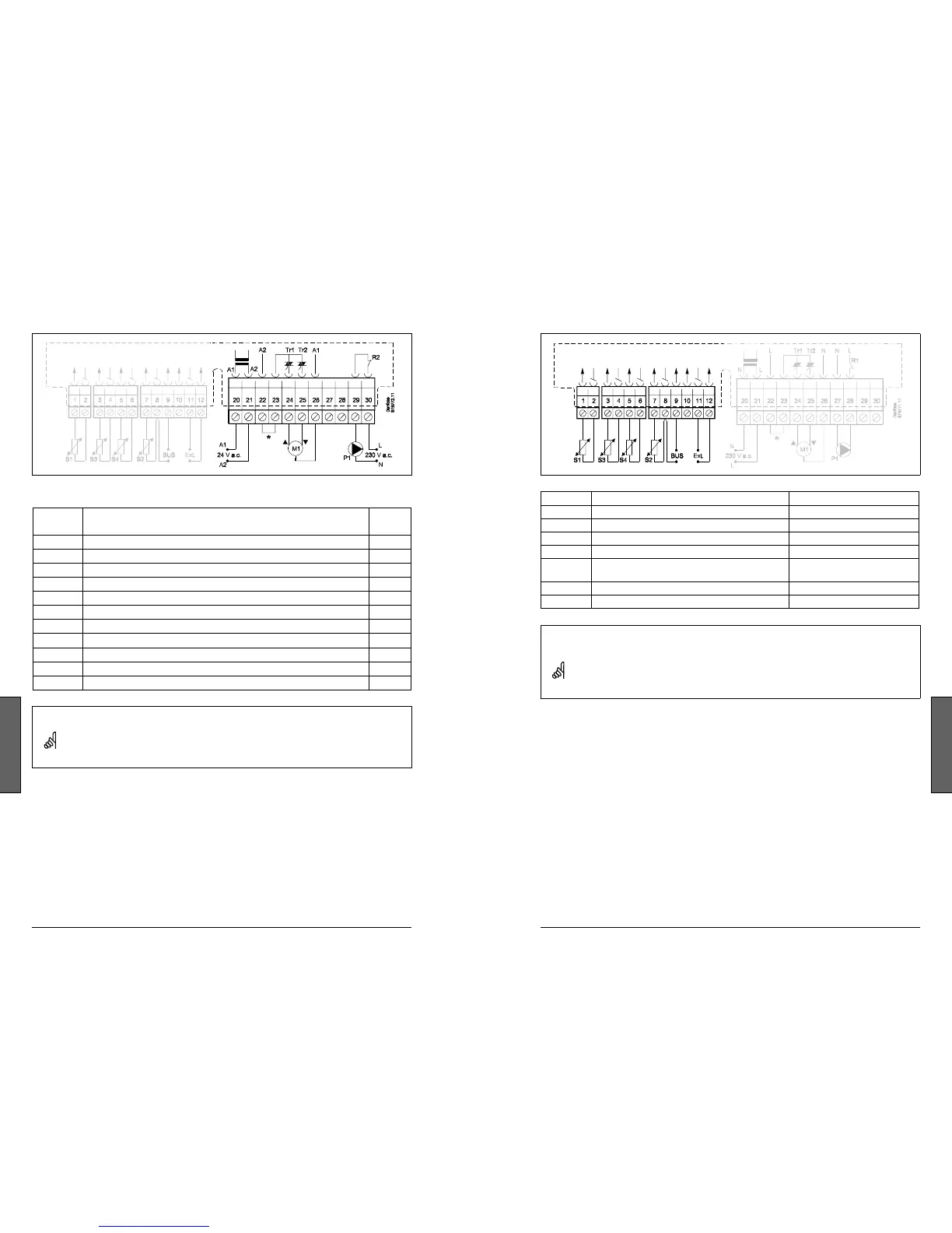
Electrical connections - 24 V a.c. - in general
Terminal Description Type (recomm.)
1 and 2 S1 Outdoor temperature sensor ESMT
3 and 4 S3 Flow temperature sensor ESM-11 / ESMC / ESMU
5 and 6 S4 Return temperature sensor ESM-11 / ESMC / ESMU
7 and 8 S2 Room temperature sensor ESM-10
8 and 9 ECL BUS, connections for room panel /
remote control
ECA 60 / 62
ECA 61 / 63
10 Not to be used
11 and 12 Ext. override
Wire cross section for sensor connections:
0.4 - 0.75 mm
2
Total cable length: Max. 125 m (all sensors incl. the ECL BUS)
Cable lengths of more than 125 m may cause noise sensibility (EMC).
Connecting the temperature sensors and the ECL BUS
 Loading...