1.4.1 Removing the Input Terminal Plate
To remove the input terminal plate, use the following
procedure. Refer to Illustration 1.2 and Illustration 1.3.
Optional components mounted on the input terminal plate
can result in diering congurations. These options include:
•
Input disconnect.
•
RFI
lter.
•
AC fuses with cooling fan.
1. Disconnect the input power wiring from terminals R
(L1), S (L2), T (L3), and ground connector.
2. Remove the uppermost retaining nut (M10) from
each of the 3 input busbars.
3. If a disconnect option (not shown) is present, remove
the disconnect from the terminal plate assembly to
reduce the weight of the terminal plate as follows:
3a Loosen the connection nut (17 mm)
between each fuse and the disconnect.
3b Remove the 4 mounting screws (T40) from
the disconnect.
3c Slide the disconnect down to clear the fuses
and remove it.
4. If the fuse option with cooling fan is present,
disconnect the cooling fan cable from the connector.
5. If the RFI lter option is present, disconnect the RFI
cable from the connector.
6. Remove the 8 retaining nuts (M6) from the input
terminal plate.
7. Lift the input terminal plate with attached input
busbars and options from the unit.
NOTICE
The terminal plate and attached options weigh up to 20 kg
(44 lb).
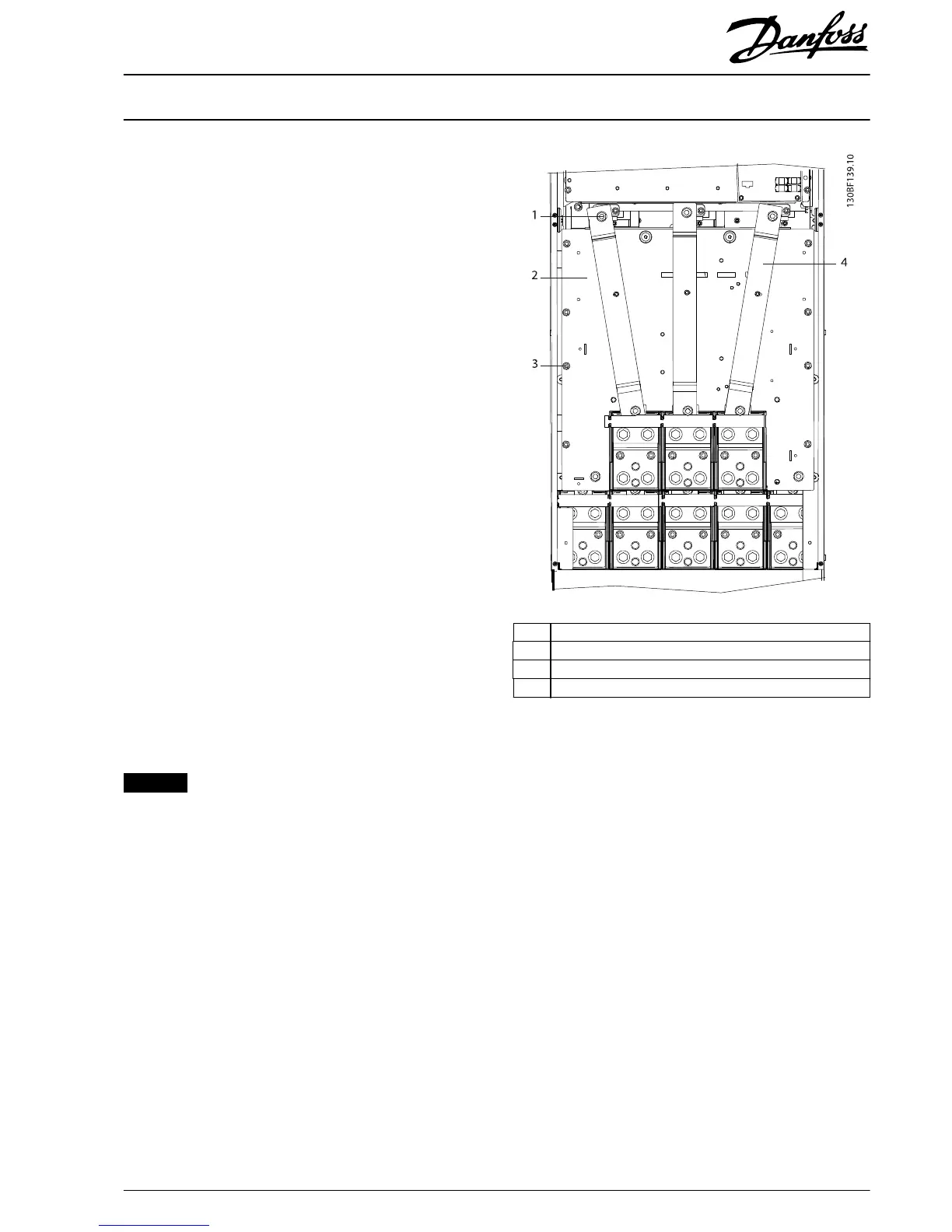
1 Upper retaining nut (M10)
2 Input terminal plate
3 Mounting plate retaining nut (M6)
4Input busbars
Illustration 1.2 Input Terminal Plate
Installation Instructions
500 A Current Sensor Kit for
E1/E2 Enclosure Sizes
VLT
®
FC 102, FC 103, FC 202, FC 302
MI92Q102 Danfoss A/S © 10/2016 All rights reserved.
3