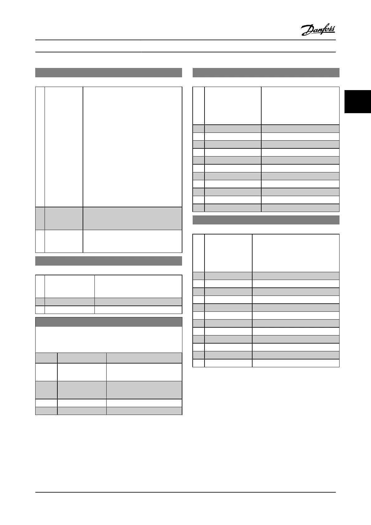
12-94 Broadcast Storm Protection
Option: Function:
The built-in switch is capable of protecting
the switch system from receiving too many
broadcast packages, which can use up
network resources. The value indicates a
percentage of the total bandwidth that is
allowed for broadcast messages.
Example:
The “OFF” means that the filter is disabled,
and all broadcast messages will be passed
through. The value “0%” means that no
broadcast messages will be passed through.
A value of “10%” means that 10% of the total
bandwidth is allowed for broadcast
messages. If the amount of broadcast
messages increases above the 10%
threshold, they will be blocked.
[0] Protection
Value Port 1
(*Off – 20%)
[1] Protection
Value Port 2
(*Off – 20%)
12-95 Broadcast Storm Filter
Option: Function:
Applies to par. 12-94; if Broadcast
Storm Protection should also include
Multicast messages.
[0] Broadcast only
[1] Broadcast & Multicast
12-96 Port Mirroring
Enables/disables port mirroring function. For troubleshooting with
a network analyzer tool.
Option: Function:
[0]
*
Disable No port mirroring
[1] Port 1 to Port 2 All network traffic on port 1 will
be mirrored to port 2.
[2] Port 2 to Port 1 All network traffic on port 2 will
be mirrored to port 1.
[254] Int. Port to Port 1
[255] Int. Port to Port 2
12-98 Interface Counters
Option: Function:
Read only. Advanced interface
counters from the built-in switch
can be used for low-level trouble-
shooting. The parameter shows the
sum of port 1 + port 2.
[0] In Octets
[1] In Unicast Packets
[2] In Non-Unicast Packets
[3] In Discards
[4] In Errors
[5] In Unknown Protocols
[6] Out Octets
[7] Out Unicast Packets
[8] Out Non-Unicast Packets
[9] Out Discards
[10] Out Errors
12-99 Media Counters
Option: Function:
Read only. Advanced interface counters
from the built-in switch can be used for
low-level troubleshooting. The
parameter shows the sum of port 1 +
port 2.
[0] Alignment Errors
[1] FCS Errors
[2] Single Collisions
[3] Multiple Collisions
[4] SQE Test Errors
[5] Deferred Errors
[6] Late Collisions
[7] Excessive Collisions
[8] MAC Transmit Errors
[9] Carrier Sense Errors
[10] Frame Too Long
[11] MAC Receive Errors
Parameter Descriptions FC 300 Programming Guide
MG.33.MA.22 - VLT
®
is a registered Danfoss trademark 3-105
3

 Loading...


