3.18 Parameters: 17-** Motor Feedb. Option
Additional parameters to configure the Encoder (MCB 102)
or the Resolver (MCB 103) Feedback Option.
3.18.1 17-1* Inc. Enc. Interface
Parameters in this group configure the incremental interface
of the MCB 102 option. Note that both the incremental and
absolute interfaces are active at the same time.
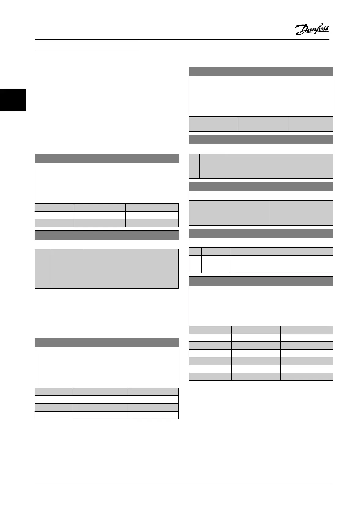
17-10 Signal Type
Select the incremental type (A/B channel) of the encoder in use.
Find the information on the encoder data sheet.
Select None [0] if the feedback sensor is an absolute encoder only.
This parameter cannot be adjusted while the motor is running.
Option: Function:
[0] None
[1]
*
TTL (5V, RS4222)
[2] SinCos
17-11 Resolution (PPR)
Range: Function:
1024
*
[10 - 10000 ] Enter the resolution of the incremental
track, i.e., the number of pulses or periods
per revolution.
This parameter cannot be adjusted while
the motor is running.
3.18.2 17-2* Abs. Enc. Interface
Parameters in this group configure the absolute interface of
the MCB 102 option. Note that both the incremental and
absolute interfaces are active at the same time.
17-20 Protocol Selection
Select HIPERFACE [1] if the encoder is absolute only.
Select None [0] if the feedback sensor is an incremental encoder
only.
This parameter cannot be adjusted while the motor is running.
Option: Function:
[0]
*
None
[1] HIPERFACE
[2] EnDat
[4] SSI
17-21 Resolution (Positions/Rev)
Select the resolution of the absolute encoder, i.e., the number of
counts per revolution.
This parameter cannot be adjusted while the motor is running. The
value depends on setting in 17-20 Protocol Selection.
Range: Function:
Application
dependent
*
[Application
dependant]
17-24 SSI Data Length
Range: Function:
13
*
[13 - 25 ] Set the number of bits for the SSI message.
Choose 13 bits for single-turn encoders and 25
bits for multi-turn encoder.
17-25 Clock Rate
Range: Function:
Application
dependent
*
[Application
dependant]
Set the SSI clock rate. With
long encoder cables the
clock rate must be reduced.
17-26 SSI Data Format
Option: Function:
[0]
*
Gray code
[1] Binary code Set the data format of the SSI data. Choose
between Gray or Binary format.
17-34 HIPERFACE Baud rate
Select the baud rate of the attached encoder.
This parameter cannot be adjusted while the motor is running. The
parameter is only accessible when 17-20 Protocol Selection is set to
HIPERFACE [1].
Option: Function:
[0] 600
[1] 1200
[2] 2400
[3] 4800
[4]
*
9600
[5] 19200
[6] 38400
Parameter Descriptions FC 300 Programming Guide
3-138 MG.33.MA.22 - VLT
®
is a registered Danfoss trademark
3

 Loading...


