6
Danfoss Randall can accept no responsibilty for possible errors in catalogues, brochures and other printed material. Danfoss Randall reserves the right to alter its products without notice. This also
applies to products already on order provided that such alterations can be made without subsequent changes being necessary in specifications already agreed.
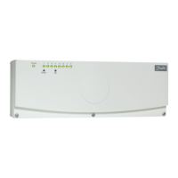
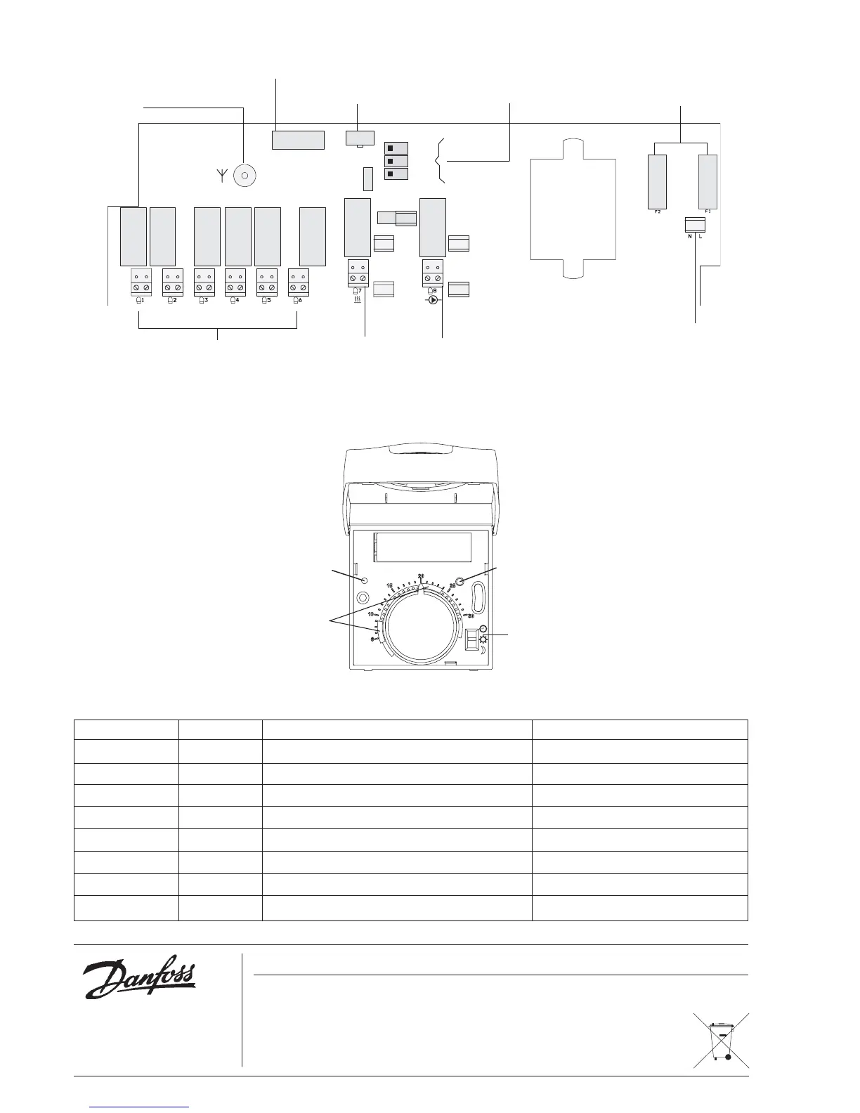
8.0 Drawing of Base Unit & Thermostat
Aerial socket
Connector for timer module
Power supply
connectors
Thermal actuators outputs 1-6
Thermal actu-
ator output 7
- alternatively:
boiler control
output
Special functions
Fuse holders
Thermal ac-
tuator output 8
- alternatively:
pump control
output
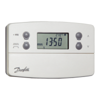
Thermostat mode switch
Transmission button
LED indicator
Min/max setting
9.0 Registration Record
Output Channel Room Circuit
1 1
2 2
3 1
4 2
5 1
6 2
7/boiler (optional) 1
8/pump (optional) 2
Connector for LEDs and buttons on lid
Danfoss Randall Limited,
Ampthill Road,
Bedford, MK42 9ER
Telephone: (01234) 364621 Fax: (01234) 219705
Email: danfossrandall@danfoss.com
Website: www.danfoss-randall.co.uk
Part No: 90092v05 09/08
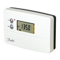
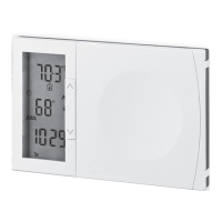
Fig. 10. Base Unit
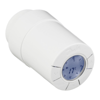
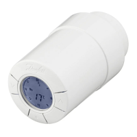
Fig. 11. Thermostat