Theory of operation
The 3-position (FNR) Electric Control uses an electric input signal to switch the pump to a full stroke
position.
Pump displacement versus electrical signal
100 %
0
100 %
Voltage Vdc
Displacement
Hydrostatic drive line power
Warning
Unintended vehicle or machine movement hazard. The loss of hydrostatic drive line power, in any mode
of operation (forward, neutral, or reverse) may cause the system to lose hydrostatic braking capacity. You
must provide a braking system, redundant to the hydrostatic transmission, sufficient to stop and hold the
vehicle or machine in the event of hydrostatic drive power loss.
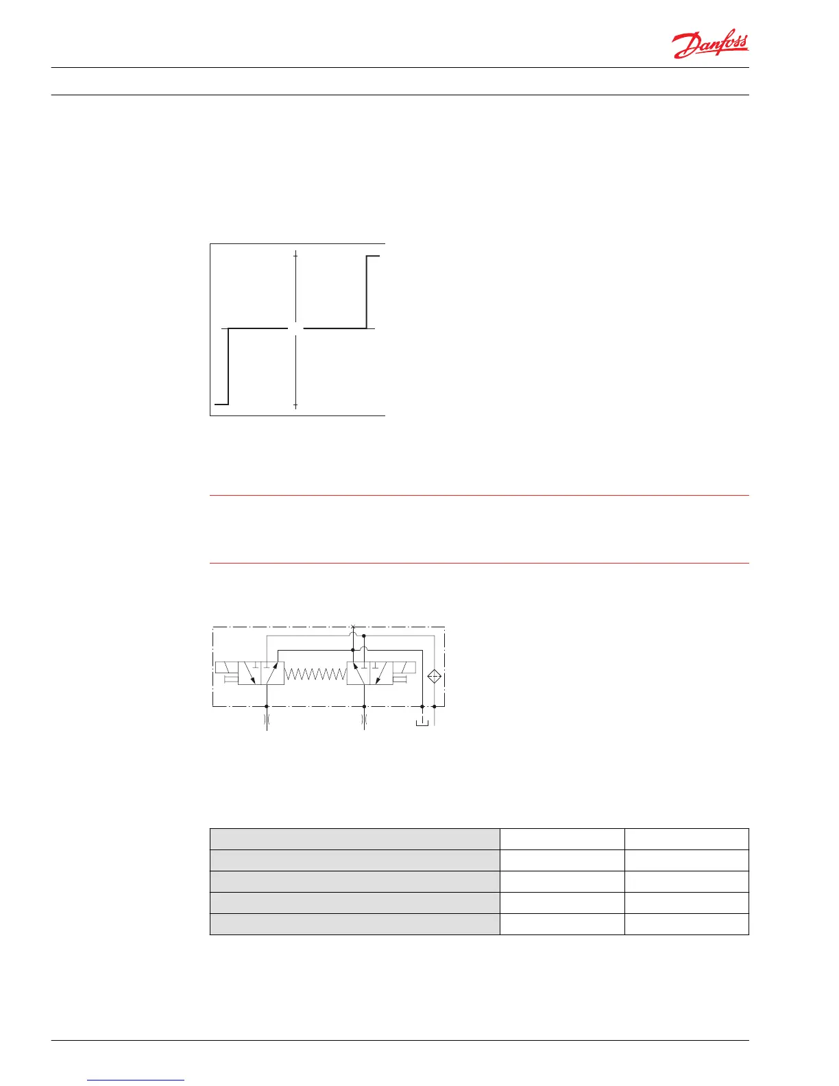
Hydraulic schematics
Electrical specifications
H1 pump 3-position (FNR) electrical specifications
Voltage
12V 24V
Minimum supply voltage
9.5 Vdc 19 Vdc
Maximum supply votage
14.6 Vdc 27 Vdc
Rated power
17 W 17 W
Coil resistance at 20º C [70º F]
8.4 Ω 34.5 Ω
Electrical Installation H1 Pump 3-Position (FNR) Electric Control
Product overview
6 11025001 • Rev BA • September 2015

 Loading...