e30bj661.11
17
15
7
3
5
2
1
9
8
6
4
13
11
10
16
14
12
18
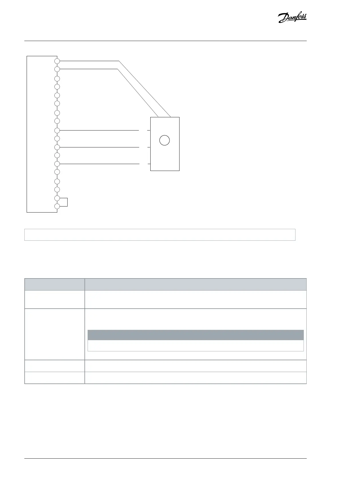
A
B
Z
1
Illustration 7: Wiring Configuration for Incremental Encoder, 3 Single Tracks (TTL, HTL)
5.5.2 Two Incremental Encoders
It is possible to connect two 2-track incremental encoders where channel 1 (A, B) supports TTL and HTL, and channel 2 (Z, D) sup-
ports only TTL.
Table 9: Parameters for 2 Incremental Encoders
9.4.1 Interface configura-
tion
Select [5] 2 track Incremental A,B + 2 track incremental Z,D.
9.4.4 Encoder Supply Volt-
age
Set the appropriate supply voltage. If the power requirement exceeds the maximum power of the
internal supply, the 2nd encoder may require external supply.
N O T I C E
Voltage can be up to 24 V. Setting the voltage too high can damage the connected encoder.
9.5.1 Resolution Device 1
Set the resolution of the encoder connected to A and B in pulses per revolution.
9.5.2 Resolution Device 2
Set the resolution of the encoder connected to Z and D in pulses per revolution.
AQ390830267692en-000601 / 136R027320 | Danfoss A/S © 2023.06
Encoder/Resolver Installation and
Configuration
Functional Extension Options
Operating Guide
 Loading...


