e30bj664.11
17
15
7
3
5
2
1
9
8
6
4
13
11
10
16
14
12
18
A+
A–
B+
B–
A+
A–
B+
B–
1
2
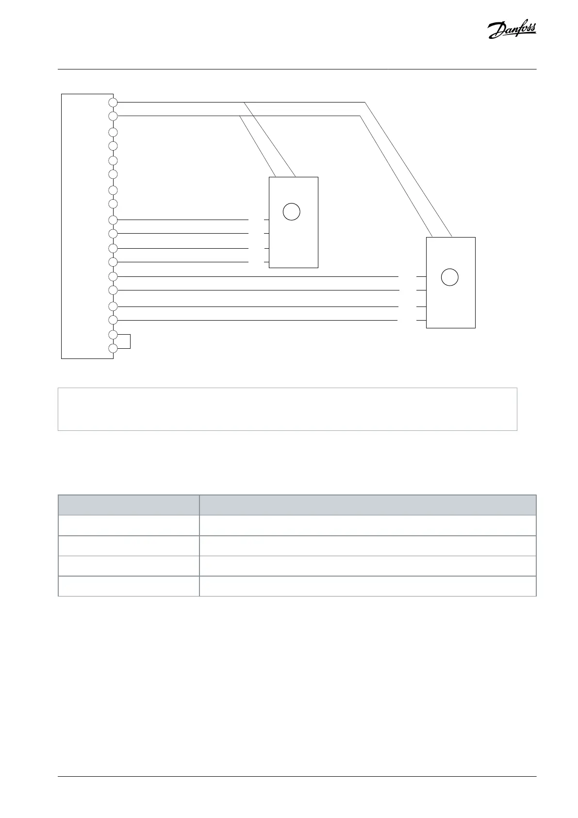
Illustration 8: Wiring Configuration for 2 Incremental Encoders
Incremental encoder, 2 differential tracks (TTL, HTL)
Incremental encoder, 2 differential tracks (only TTL on Z and D). This encoder may require a separate supply.
5.5.3 Resolver
With a resolver, the actual position is set to the absolute value within 1 resolver pole pair based on the analog value of the sine and
cosine signals. With a 2-pole resolver, this corresponds to the absolute position within 1 resolver revolution.
Table 10: Parameters for Resolver
9.4.1 Interface configuration
Set the excitation voltage according to the resolver specifications.
9.7.2 Excitation Frequency
Set the excitation frequency according to the resolver specifications.
Set the number of poles for the connected resolver.
AQ390830267692en-000601 / 136R0273 | 21Danfoss A/S © 2023.06
Encoder/Resolver Installation and
Configuration
Functional Extension Options
Operating Guide
 Loading...


